ANTI-LOCK BRAKES
Anti-lock Brake Wiring Diagrams for Dodge Avenger 1998
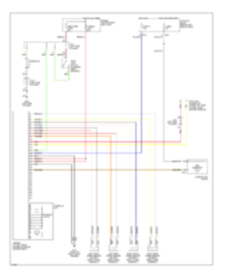
List of elements for Anti-lock Brake Wiring Diagrams for Dodge Avenger 1998:
- Abs indicator
- Abs-ecu (at left front corner of engine compartment)
- B-54
- C-06
- Combination meter
- Data link connector (under left side of dash, near center console)
- Dedicated fuse 1 20a
- Engine compartment relay box
- Fuse 13 10a
- Fuse 8 10a
- Fusible link 7 50a
- G101 (front of right front fender)
- G202 (left side of dash)
- Hot at all times
- Hot in on
- Hot in on or start
- Hydraulic unit
- J/c 1 (left side of dash)
- J/c 2 (left side of dash)
- Junction block (behind left side of dash)
- Left front speed sensor (on left front wheel assembly)
- Left rear speed sensor (on left rear wheel assembly)
- Nca
- Pnk
- Resistor
- Right front speed sensor (on right front wheel assembly)
- Right rear speed sensor (on right rear wheel assembly)
- Solenoid valve
- Stop light switch (on brake pedal bracket)
 English