ANTI-LOCK BRAKES
Anti-lock Brake Wiring Diagrams for Dodge Cab & Chassis R3500 2001
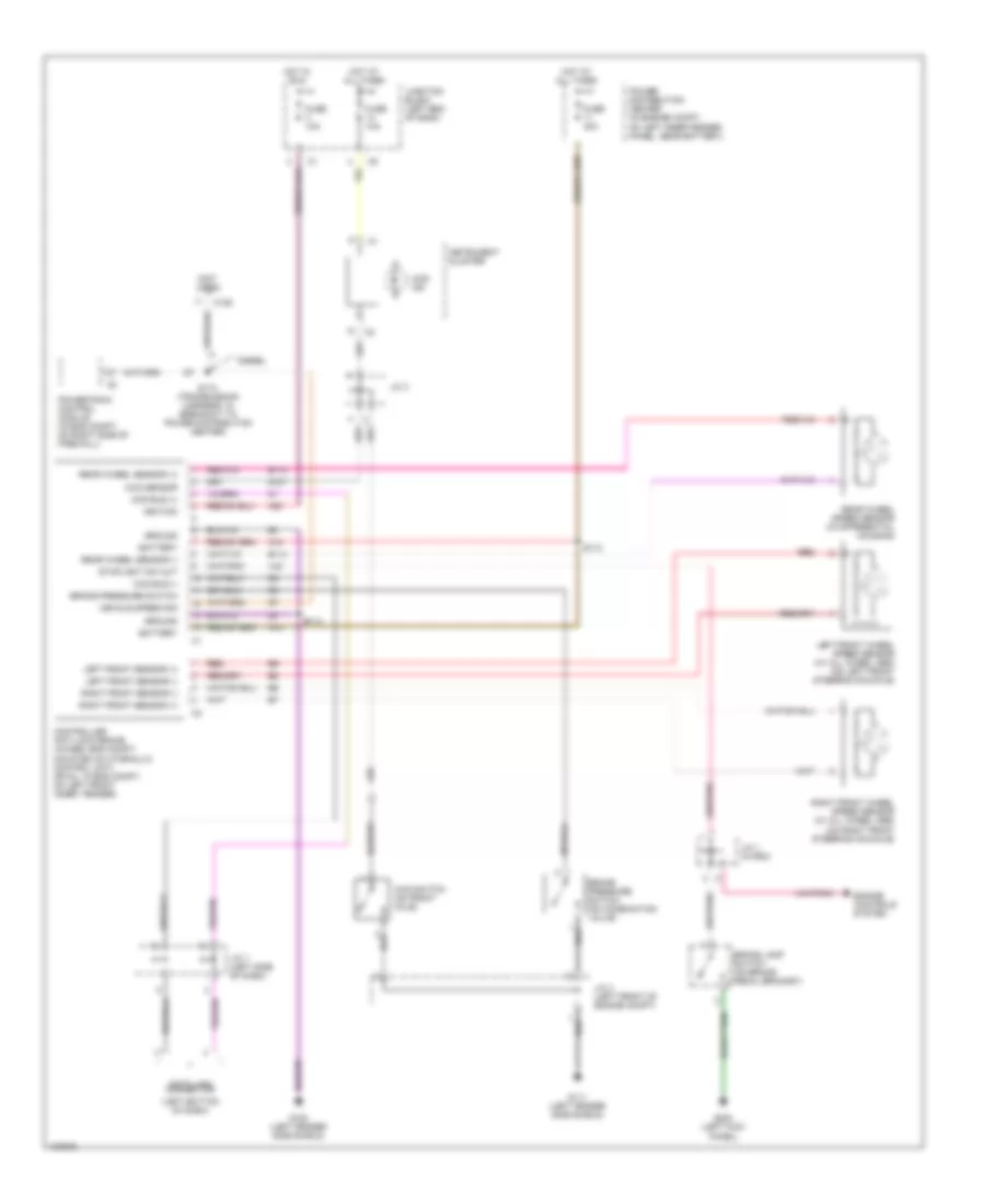
List of elements for Anti-lock Brake Wiring Diagrams for Dodge Cab & Chassis R3500 2001:
- (left bottom of dash)
- (not used)
- 4wd ind
- 4wd sensor
- 4wd switch (on front axle)
- A10
- A20
- B113
- B114
- Battery
- Brake lamp switch (on brake pedal bracket)
- Brake pressure switch
- Brake pressure switch (on combination valve)
- C125
- Ccd bus (+)
- Ccd bus (-)
- Controller anti-lock brake (4wabs: eng compt, mounted on hydraulic control unit) (rwal: in eng compt, on left front inner fender)
- Data link connector
- Diesel
- Engine controls system
- Fuse 10a
- Fuse 40a
- G100 (left fender side shield)
- G107
- G111 (left fender side shield)
- G200 (left kick panel)
- Ground
- Hot at all times
- Hot in run
- Ignition
- Instrument cluster
- J/c 1 (in pdc)
- J/c 3
- J/c 4 (left front of engine compt)
- J/c 7 (left side of dash)
- Junction block (left end of dash)
- Left front sensor (+)
- Left front sensor (-)
- Left front wheel speed sensor (w/ all wheel abs) (on left front steering knuckle)
- Power distribution center (in engine compt, on left inner fender panel, near battery)
- Powertrain control module (in eng compt, on right side of firewall)
- Rear wheel sensor (+)
- Rear wheel sensor (-)
- Rear wheel speed sensor (in differential housing)
- Red
- Right front sensor (+)
- Right front sensor (-)
- Right front wheel speed sensor (w/ all wheel abs) (on right front steering knuckle)
- S112
- S113
- S174 (transmission harness, in breakout to power distribution center)
- Stoplight sw out
- V40
- Vehicle speed sig
 English