ANTI-LOCK BRAKES
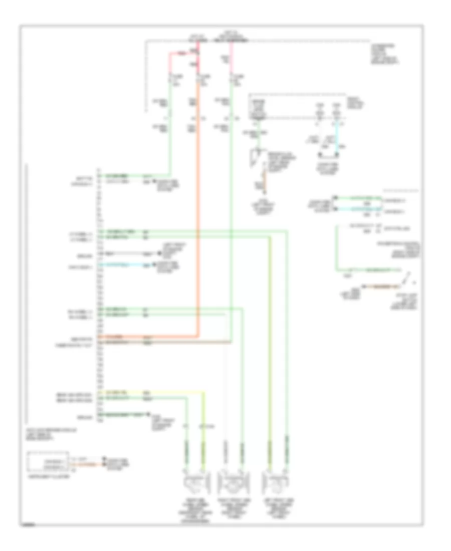
Anti-lock Brakes Wiring Diagram for Dodge Dakota 2010
List of elements for Anti-lock Brakes Wiring Diagram for Dodge Dakota 2010:
- (left front of engine compt) g100
- A107
- A111
- Abs pmp fd
- Anti-lock brakes module (left side of engin ecompt)
- B22
- B222
- B29
- Batt fd
- Brake fluid level sensor (left rear of engine compt)
- Brake fluid level switch sense
- C105
- C201
- Can bus (+)
- Can bus (-)
- Can c bus (+)
- Can c bus (-)
- Computer data lines system
- D64
- D65
- F500
- Front control module
- Fuse 20a
- Fuse 40a
- Fused run rly out
- G100 (left front of engine compt)
- G200 (left side of dash)
- Ground
- Hot at all times
- Hot w/ ignition run relay energized
- Instrument cluster
- Integrated power module (left side of engine compt)
- Left front abs wheel speed sensor (left front wheel)
- Lf wheel (+)
- Lf wheel (-)
- Powertrain control module (right side of engine compt)
- Rear abs wheel speed sensor (near right rear wheel, by crossmember)
- Rear veh spd sig1
- Rear veh spd sig2
- Red
- Rh wheel (+)
- Rh wheel (-)
- Right front abs wheel speed sensor (right front wheel)
- Stop lamp switch (lower left side of dash)
- Stp ctrl sig
- Tan/ red
- Tan/red
- Z107
- Z923
 English