ANTI-LOCK BRAKES
Anti-lock Brake Wiring Diagrams for Dodge Durango 2001
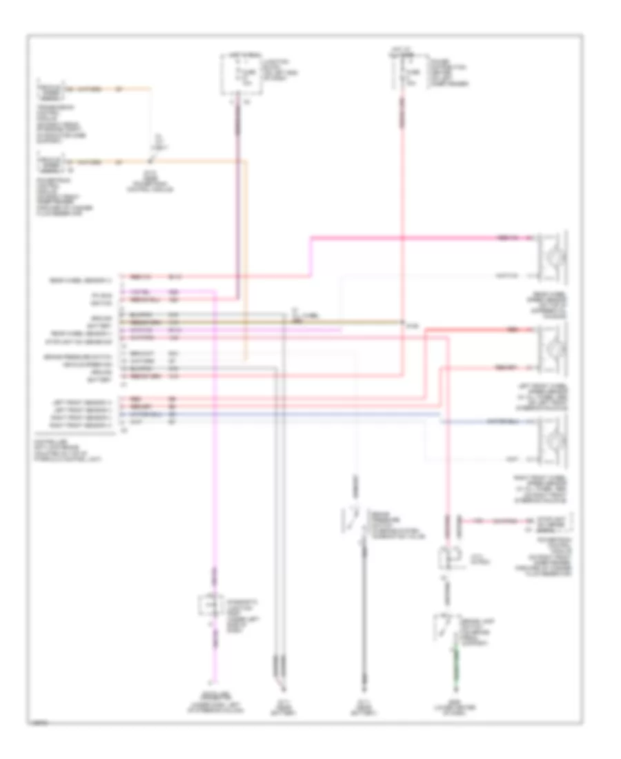
List of elements for Anti-lock Brake Wiring Diagrams for Dodge Durango 2001:
- (under dash, left of steering column)
- A10
- A20
- B10
- B113
- B114
- Battery
- Brake lamp switch (on brake pedal support)
- Brake pressure switch
- Brake pressure switch (in brake system combination valve)
- Controller anti-lock brake (mounted on top of hydraulic control unit)
- D25
- Data link connector
- Diagnostic junction port (under left side of dash)
- Forward of washer fluid reservoir)
- Fuse 10a
- Fuse 40a
- G111 (near battery)
- G206 (lower center of dash)
- Ground
- Hot at all times
- Hot in run
- Ignition
- J/c 2 (in pdc)
- Junction block (on left end of dash)
- Left front sensor (+)
- Left front sensor (-)
- Left front wheel speed sensor (w/ all wheel abs) (on left front steering knuckle)
- On radiator core support)
- Pci bus
- Power distribution center (on left inner fender)
- Powertrain control module (on right front inner fender,
- Powertrain control module (on right front inner fender, forward of washer fluid reservoir)
- Rear wheel sensor (+)
- Rear wheel sensor (-)
- Rear wheel speed sensor (on top of differential housing)
- Red
- Right front sensor (+)
- Right front sensor (-)
- Right front wheel speed sensor (w/ all wheel abs) (on right front steering knuckle)
- S126
- S174 (near powertrain control module)
- Stoplight sw sense sig
- Stoplight sw sense signal
- Transmission control module (on right front of engine compt,
- V40
- Vehicle speed sig
- Vehicle speed signal
- W/ a/t only
- W/ all wheel abs
- Z19
 English