ANTI-LOCK BRAKES
Anti-lock Brakes Wiring Diagram for Dodge Grand Caravan Sport 2003
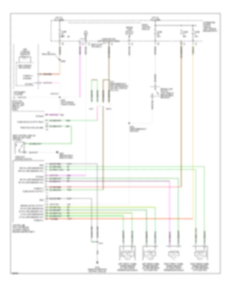
List of elements for Anti-lock Brakes Wiring Diagram for Dodge Grand Caravan Sport 2003:
- (hazard)
- 20a
- 25a
- 40a
- A107
- A111
- Abs warning ind control
- Abs warning indicator
- Assy.plant evac&fill
- B27
- Body control module (behind left side of dash)
- Brake lamp switch (left side of brake pedal bracket)
- Brake lamp switch output
- Brake lmp sw output
- Controller antilock brake (on right side of engine compartment)
- D25
- Data link connector (below left side of dash)
- Eatx
- F500
- Front control module
- Fuse
- Fuse b (+)
- Fuse ign sw output
- Fuse ign sw output (run)
- Fuse ignition switch output (run)
- G100 (near powertrain control module)
- G200 (behind right side of dash)
- Gnd
- Hot at all times
- Instrument cluster
- Integrated power module (left side of engine compt)
- L50
- Left front wheel speed sensor (at left front fender side shield)
- Left rear wheel speed sensor (at center rear of floor pan)
- Lf whl spd sensor (12v)
- Lf whl spd sensor sig
- Lr whl spd sensor (12v)
- Lr whl spd sensor sig
- Mtx
- Pci bus
- Rf whl spd sensor (12v)
- Rf whl spd sensor sig
- Right front wheel speed sensor (at right front fender side shield)
- Right rear wheel speed sensor (at center rear of floor pan)
- Rr whl spd sensor (12v)
- Rr whl spd sensor sig
- S141
- S206
- S302 (in floorpan track wiring)
- S304 (near breakout for c307)
- Tan/red
- Traction control switch
- Traction ctrl sw sen
- W/ highline only
- Z107
- Z127
 English