ANTI-LOCK BRAKES
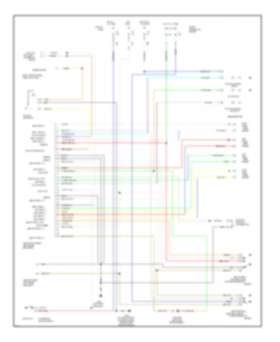
Anti-lock Brake Wiring Diagrams for Dodge Intrepid 1996
List of elements for Anti-lock Brake Wiring Diagrams for Dodge Intrepid 1996:
- (above park
- (asdm) bracket)
- (center console)
- (left fender
- (left front
- (mounted on side
- (mounted on side of
- (on airbag system
- (on reservoir)
- (on steering
- (right kick panel)
- 10a
- 20a
- 30a
- 40a
- Abs control module
- Abs diode
- Abs main relay
- Abs main relay ctrl
- Abs main relay in
- Abs motor relay
- Abs motor relay in
- Abs pump motor
- Active ind
- All times
- And start
- Anti/lock ind
- Block
- Body control module
- Brake assembly)
- Brake sw 1
- Brake warn lt sw
- C111
- C201
- C202
- Center
- Center)
- Column support)
- Column)
- Conn (right
- Control sw
- Data link
- Diagnostic module
- Dimmer control
- Distribution
- F14
- Frame rail)
- Front
- Fused b+
- G100
- G206
- Ground
- Hot
- Hot at
- Hot at all times
- Hot in run
- Ignition feed
- In run
- Junction
- Left
- Left front (+)
- Left front (/)
- Left rear (+)
- Left rear (/)
- Low fluid
- Message center
- Of power distribution
- Of steering
- Off ind
- Power
- Power distribution
- Rear
- Red
- Red b9
- Relay coil (b/)
- Right
- Right front (+)
- Right front (/)
- Right rear (+)
- Right rear (/)
- Sensor
- Serial buss (/)
- Serial buss b(+)
- Side shield)
- Stop lt sw
- Tca ind control
- Tcf ind control
- Traction
- Traction control
- Traction control sw
- Warning ind
- Wheel
 English