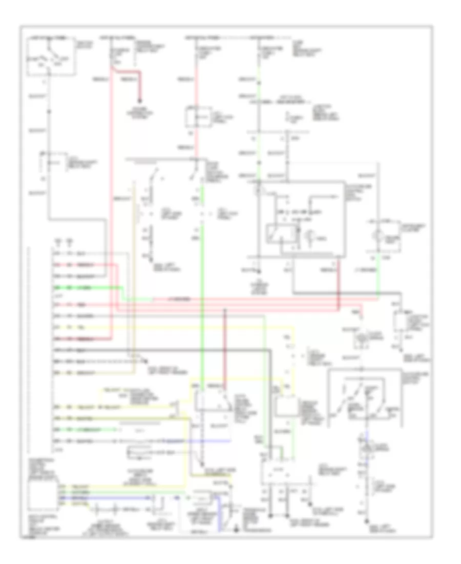
CRUISE CONTROL
Cruise Control Wiring Diagram for Dodge Avenger 1998
List of elements for Cruise Control Wiring Diagram for Dodge Avenger 1998:
- (a/t)
- (front of
- (left
- (left side
- (near center console)
- 2.0l
- 2.5l
- A-77
- A-78
- A/t
- Acc
- Accel/ resume
- Auto- cruise control relay (right side of fire- wall)
- Auto-cruise control main switch
- Auto-cruise control switch
- Auto-cruise servo (right side of safety wall)
- B-41
- B-54
- B-63
- C-06
- Cancel
- Clock spring
- Coast/ set
- Cruise indic.
- Data link connector b-30
- Dedicated fuse 1 20a
- Dedicated fuse 4 15a
- Eatx control module (a/t) (below center console)
- Engine compartment relay box
- Fuse 8 10a
- Fuse box (engine compt. relay box)
- Fusible link 40a
- G100 left front fender)
- G116 of firewall)
- G202 side of dash)
- Hot at all times
- Hot in acc,
- Hot in park
- Ignition switch
- Illum.
- Indic.
- Input speed sensor (left front of trans.)
- Instrument cluster
- J/c 1 (left kick panel)
- J/c 2 (left side of dash)
- J/c 3 (engine compt. relay box)
- J/c 4 (engine compt. relay box)
- Junction block (behind left side of dash)
- Junction block (left kick panel)
- Lock
- M/t
- Off
- Output speed sensor (on transmission, at left output shaft)
- Power distribution system
- Powertrain control module (left side of engine compt)
- Red
- Run or start
- Start
- Stop lamp switch (on brake pedal)
- To interior lights system
- Transaxle range sensor (on top of transmission)
- Vehicle speed sensor (dohc m/t) (left front of trans.)
 English