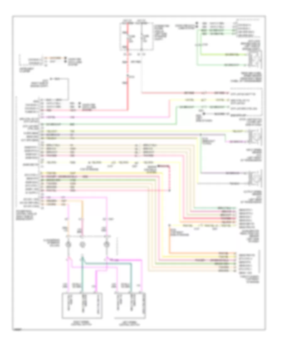
CRUISE CONTROL
Cruise Control Wiring Diagram for Dodge Dakota 2010
List of elements for Cruise Control Wiring Diagram for Dodge Dakota 2010:
- A919
- Accelerator pedal position sensor (left side of dash)
- Anti-lock brakes module (left side of engine compt)
- B22
- B222
- B29
- C105
- C107
- C201
- Can bus (+)
- Can bus (-)
- Clockspring (steering column)
- Computer data lines system
- D64
- D65
- Engine controls system
- Etc mtr (+)
- Etc mtr (-)
- F855
- F856
- Fuse 15a
- Fuse 20a
- Fused b (+)
- G107 (right side of engine compt)
- G200 (left side of dash)
- Gnd
- Gnd stp lmp
- Hot at all times
- In spd sens
- Input speed sensor (a/t) (left front of transmission)
- Instrument cluster
- Integrated power module (left side of engine compt)
- K122
- K22
- K23
- K29
- K400
- K447
- K448
- K922
- Left speed control switch
- Out spd sens
- Output speed sensor (a/t) (left rear of transmission)
- Pnk/red
- Powertrain control module (right side of engine compt)
- Rdnt fd sw cpd ctrl
- Rdnt fd sw spd ctrl
- Rear abs wheel speed sensor (near right rear wheel, by crossmember)
- Red
- Right speed control switch
- S/c sw 1 sig
- S/c sw 2 sig
- S/c sw return
- S119 (breakout to pcm)
- S122 (top right side of engine)
- S124 (top of engine)
- S133
- Sens 1 sig
- Sens gnd
- Sens prim fd
- Sens rtn
- Sens rtn 1
- Sens rtn 2
- Sens sec fd
- Sens sig 1
- Sens sig 2
- Snsr 1 sig
- Snsr rtn 1
- Snsr rtn 2
- Snsr rtn eng ctr2l com
- Snsr rtn eng ctrl com
- Snsr sec fd
- Snsr sig 1
- Snsr sig 2
- Spd ctrl fd to stp lmp sw
- Spd ctrl sw fd
- Stop lamp switch (lower left side of dash)
- Stp lmp spd ctrl sig
- Stp lmp sw batt fd
- T14
- T52
- Throttle body (top front of engine)
- V32
- V71
- V72
- V937
- Veh spd sig 1
- Veh spd sig 2
- Z913
 English