SUPPLEMENTAL RESTRAINTS
Supplemental Restraint Wiring Diagram for Dodge Avenger ES 1995
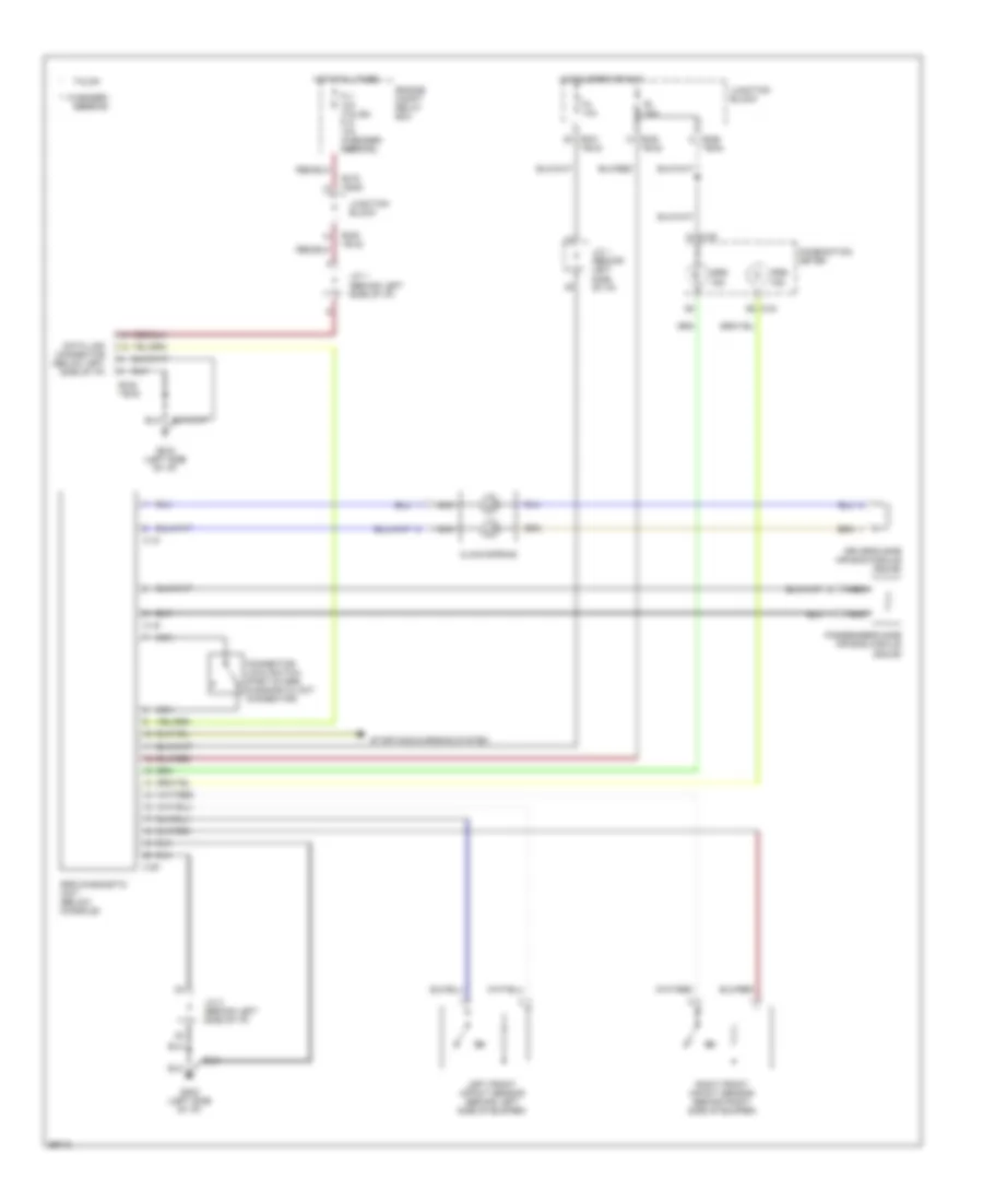
List of elements for Supplemental Restraint Wiring Diagram for Dodge Avenger ES 1995:
- ** avenger/
- **b-42
- *b-38 **b-30
- *b-50
- *b-50 **b-42
- *b-51 **b-43
- *b-66 **b-54
- *b-75 **b-63
- C-04
- C-05
- C-18
- C-19
- C-20
- Clock spring
- Combination meter
- Connector lock switch (part of srs diagnostic unit connector)
- Data link connector (below left side of i/p)
- Driver's side air bag module (squib)
- Engine compt relay box
- F11 10a (talon) f10 10a (avenger/ sebring)
- F4 10a
- F8 10a
- G202 (left side of i/p)
- Hot at all times
- Hot in start or run
- J/c 1 (behind left side of i/p)
- J/c 2 (behind left side of i/p)
- Junction block
- Left front impact sensor (behind left side of bumper)
- Nca
- Passenger's side air bag module (squib)
- Right front impact sensor (behind right side of bumper)
- Sebring
- Srs diagnostic unit (below console)
- Srs ind.
- Starting/charging system
- Talon
 English