AIR CONDITIONING
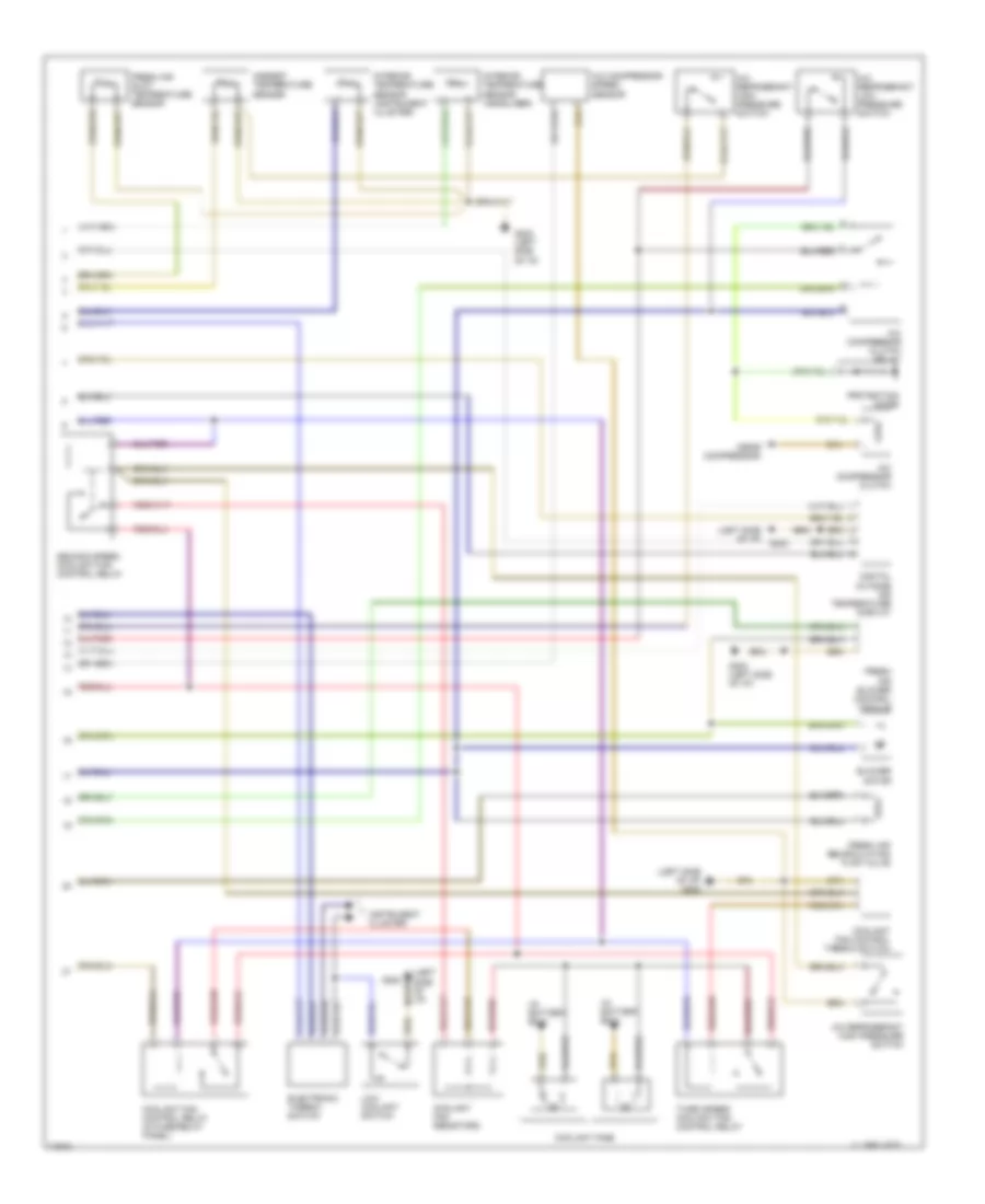
Automatic A/C-Heater System Wiring Diagram (With Automatic Transmission Wiring Diagram, A/T 1 Of for Audi 90 Sport 1995

List of elements for Automatic A/C-Heater System Wiring Diagram (With Automatic Transmission Wiring Diagram, A/T 1 Of for Audi 90 Sport 1995:
- (left side of i/p)
- 1995 vftc c
- A/c control head
- Air flow flap motor
- Auxiliary relay panel 2
- B10
- Battery (30)
- C10
- C11
- Central flap motor potentiometer
- Data link connector
- Engine control module
- Footwell/defrost flap motor potentiometer
- Fuse 15a
- Fuse 25a
- Fuse 30a
- Fuse 5a
- Fuse 60a
- Fuse/ relay panel
- G202 (left side of i/p)
- Hot at all times
- Hot w/ lights on
- Hot w/ load reduction relay energized (x)
- Ignition (15)
- Interior temperature sensor fan
- Temp regulator flap motor potentiometer
- Transmission control module
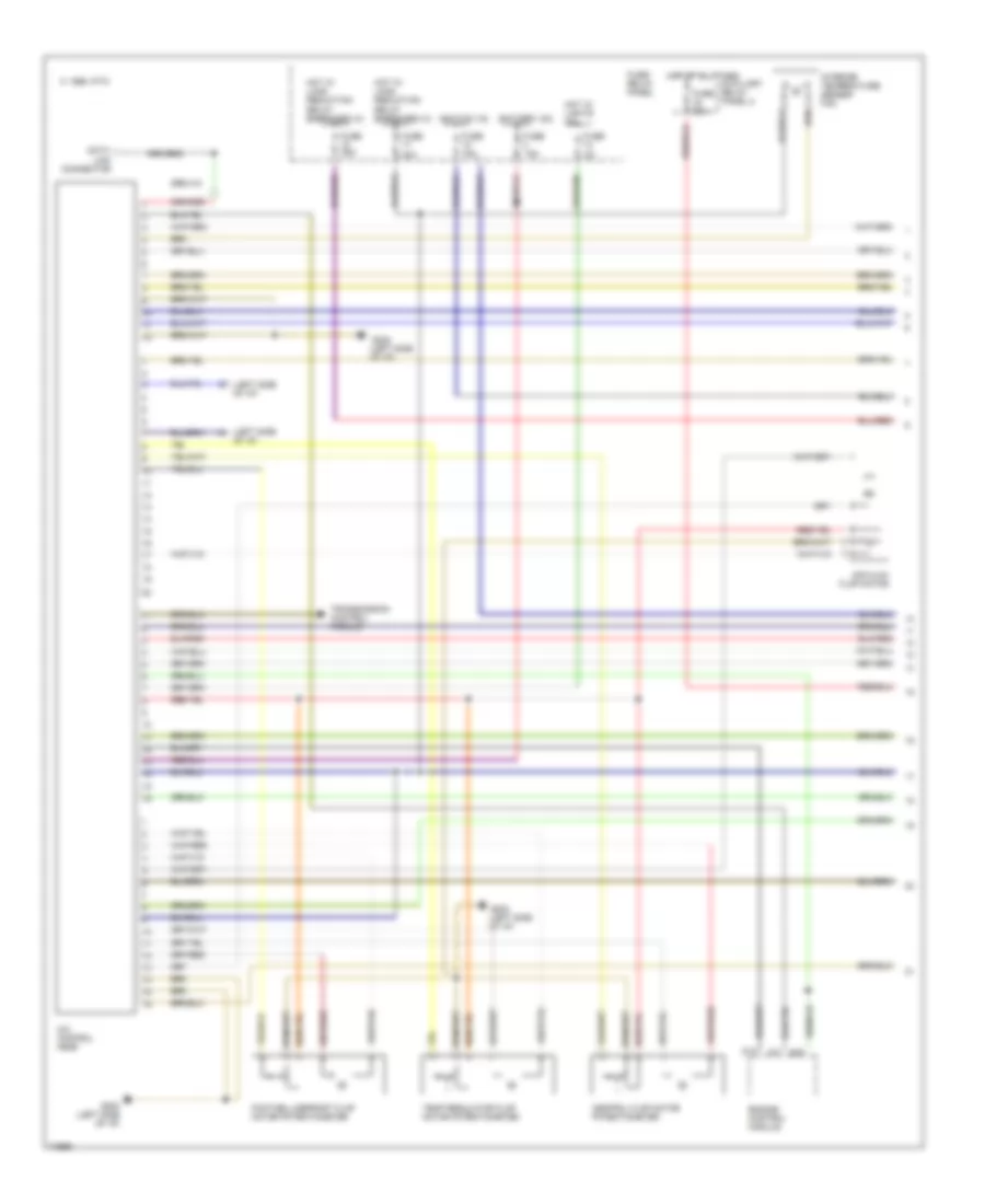
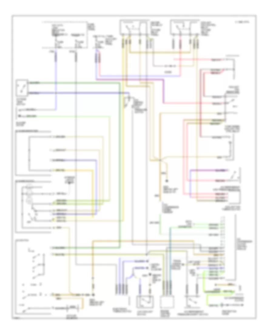
Automatic A/C-Heater System Wiring Diagram (With Automatic Transmission Wiring Diagram, A/T 2 Of for Audi 90 Sport 1995
List of elements for Automatic A/C-Heater System Wiring Diagram (With Automatic Transmission Wiring Diagram, A/T 2 Of for Audi 90 Sport 1995:
- (in battery box)
- (left side of i/p)
- (left side of i/p) g202
- (near compressor)
- 1995 vftc c
- A/c compressor clutch
- A/c compressor clutch relay
- A/c compressor speed sensor
- A/c refrigerant high pressure switch
- A/c refrigerant low pressure switch
- Ambient temperature sensor
- Blower motor
- Coolant fan control relay (in fuse/relay panel)
- Coolant fan control thermo switch
- Coolant fan resistors
- Coolant fans
- Digital outside air temperature display
- Electronic thermo switch
- Fresh air blower control module
- Fresh air duct temperature sensor
- Fresh air recirculating flap valve
- G202
- G202 (left side of i/p)
- Instrument cluster
- Interior temperature sensor (headliner)
- Interior temperature sensor (instrument cluster)
- Low coolant switch
- Protection diode
- Second speed coolant fan control relay
- Third speed coolant fan control relay
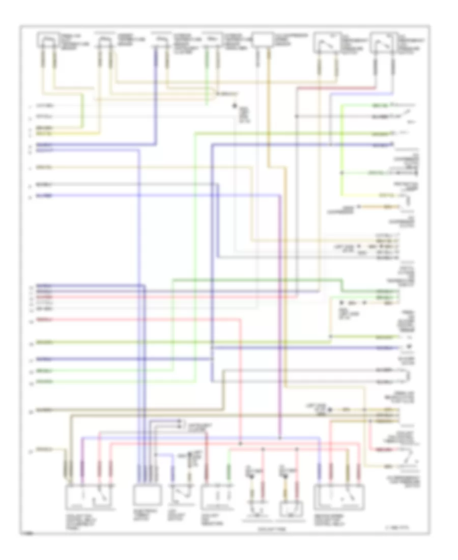
Automatic A/C-Heater System Wiring Diagram (With Manual Transmission Wiring Diagram, M/T 1 Of 2) for Audi 90 Sport 1995
List of elements for Automatic A/C-Heater System Wiring Diagram (With Manual Transmission Wiring Diagram, M/T 1 Of 2) for Audi 90 Sport 1995:
- (left side of i/p)
- 1995 vftc c
- A/c control head
- Air flow flap motor
- Auxiliary relay panel 2
- B10
- Battery (30)
- C10
- C11
- Central flap motor potentiometer
- Data link connector
- Engine control module
- Footwell/defrost flap motor potentiometer
- Fuse 15a
- Fuse 25a
- Fuse 30a
- Fuse 5a
- Fuse 60a
- Fuse/ relay panel
- G202 (left side of i/p)
- Hot at all times
- Hot w/ lights on
- Hot w/ load reduction relay energized (x)
- Ignition (15)
- Interior temperature sensor fan
- Temp regulator flap motor potentiometer
- Transmission control module
Automatic A/C-Heater System Wiring Diagram (With Manual Transmission Wiring Diagram, M/T 2 Of 2) for Audi 90 Sport 1995
List of elements for Automatic A/C-Heater System Wiring Diagram (With Manual Transmission Wiring Diagram, M/T 2 Of 2) for Audi 90 Sport 1995:
- (in battery box)
- (left side of i/p)
- (left side of i/p) g202
- (near compressor)
- 1995 vftc c
- A/c compressor clutch
- A/c compressor clutch relay
- A/c compressor speed sensor
- A/c refrigerant high pressure switch
- A/c refrigerant low pressure switch
- Ambient temperature sensor
- Blower motor
- Coolant fan control relay (in fuse/relay panel)
- Coolant fan control thermo switch
- Coolant fan resistors
- Coolant fans
- Digital outside air temperature display
- Electronic thermo switch
- Fresh air blower control module
- Fresh air duct temperature sensor
- Fresh air recirculating flap valve
- G202
- G202 (left side of i/p)
- Instrument cluster
- Interior temperature sensor (headliner)
- Interior temperature sensor (instrument cluster)
- Low coolant switch
- Protection diode
- Second speed coolant fan control relay
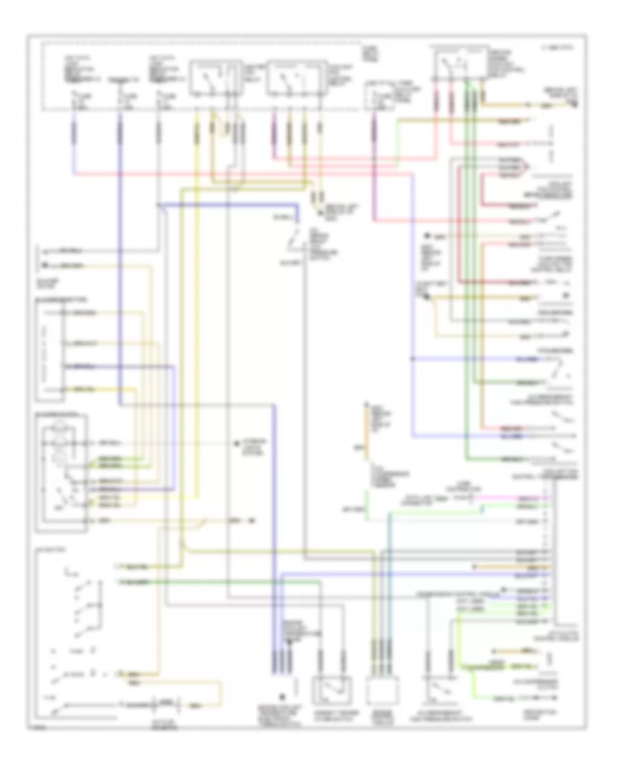
Manual A/C Wiring Diagram, A/T for Audi 90 Sport 1995
List of elements for Manual A/C Wiring Diagram, A/T for Audi 90 Sport 1995:
- (behind left side of i/p) g202
- (in battery box) g100
- (near compressor)
- (not used)
- 1995 vftc c
- A/c clutch control module
- A/c compressor clutch
- A/c compressor speed sensor
- A/c flap solenoid
- A/c refrig- erant low pressure switch
- A/c refrigerant
- A/c refrigerant high pressure switch
- A/c switch
- Ambient temper- ature switch
- Auxiliary relay panel
- B10
- Blower motor
- Blower resistors
- Blower switch
- C10
- C11
- Coolant fan
- Coolant fan control relay
- Coolant fan control series resistors
- Coolant fan control thermoswitch
- Data link connector
- Engine control module
- Engine coolant temperature electronic thermo switch
- Engine coolant temperature gauge
- Fuse 15a
- Fuse 25a
- Fuse 30a
- Fuse 60a
- Fuse/ relay panel
- G202 (behind left side of i/p)
- Heater fan
- High pressure switch
- Hot at all times
- Hot with load reduction relay energized (x)
- Ignition (15)
- Interior lights system
- Off
- Protection diode
- Relay
- Second speed coolant fan control relay
- Third speed coolant fan control relay
- Transmission control module
- Wire distributor
Manual A/C Wiring Diagram, M/T for Audi 90 Sport 1995
List of elements for Manual A/C Wiring Diagram, M/T for Audi 90 Sport 1995:
- (behind left side of i/p)
- (left side i/p)
- (left side of i/p)
- (near compressor)
- 1995 vftc c
- A/c compressor clutch
- A/c compressor clutch control module
- A/c compressor speed sensor
- A/c flap solenoid
- A/c refrig- erant low pressure switch
- A/c refrigerant
- A/c refrigerant high pressure switch
- A/c switch
- Auxiliary relay panel
- B10
- Blower motor
- Blower resistors
- Blower switch
- C10
- C11
- Coolant fan control relay (in fuse/ relay panel)
- Coolant fan resistors
- Coolant fan thermo switch
- Data link connector
- Diode
- Electronic thermo switch
- Engine control module
- Fuse 15a
- Fuse 30a
- Fuse 60a
- Fuse/ relay panel
- G202
- G202 (behind left side of i/p)
- Heater fan relay (in fuse/ relay panel)
- Hot at all times
- Hot with load reduction relay energized (x)
- Ignition (15)
- Instru- ment cluster
- Interior lights system
- Low coolant switch
- Off
- Outside temp switch
- Pressure safety switch
- Protection diode
- Third speed coolant fan ctrl relay
- Trans- mission control module