AIR CONDITIONING
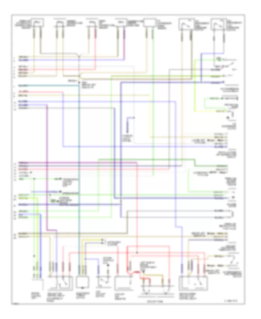
Automatic A/C-Heater System Wiring Diagram (1995 (Early Production) Wiring Diagram 1 Of 2) for Audi A6 1995

List of elements for Automatic A/C-Heater System Wiring Diagram (1995 (Early Production) Wiring Diagram 1 Of 2) for Audi A6 1995:
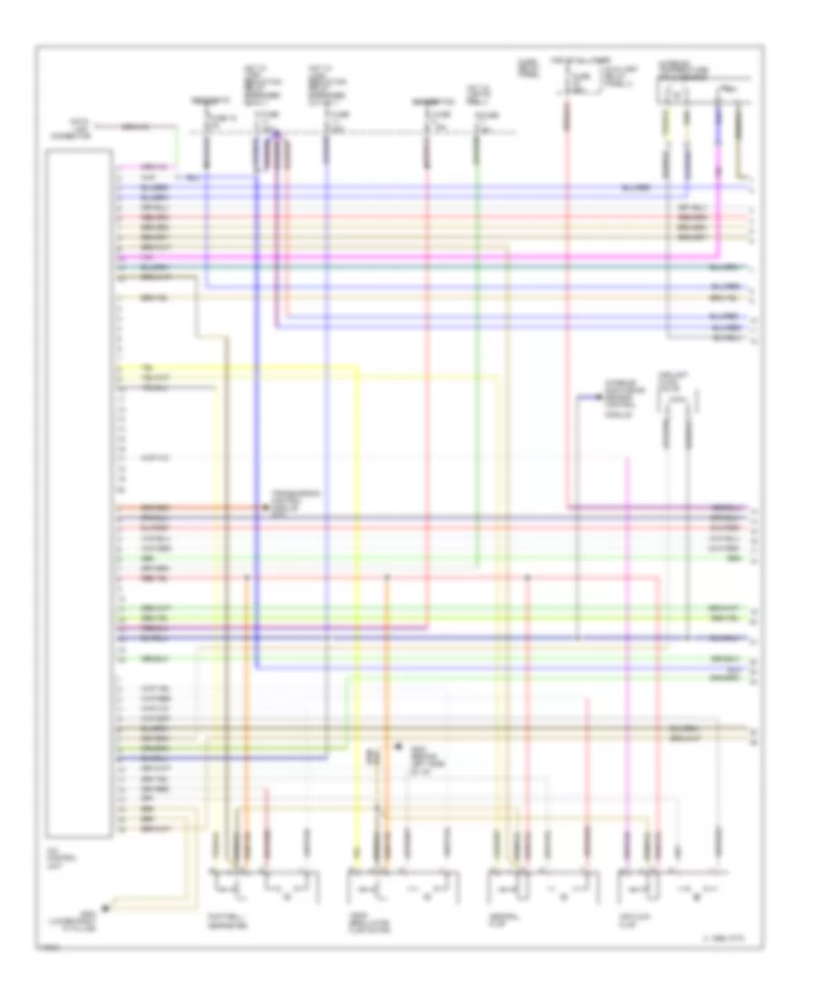
Automatic A/C-Heater System Wiring Diagram (1995 (Early Production) Wiring Diagram 2 Of 2) for Audi A6 1995
List of elements for Automatic A/C-Heater System Wiring Diagram (1995 (Early Production) Wiring Diagram 2 Of 2) for Audi A6 1995:
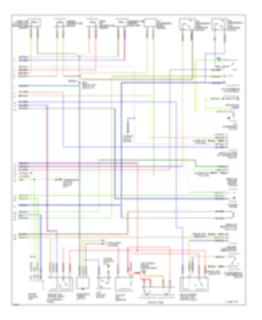
Automatic A/C-Heater System Wiring Diagram (1995 (Late Production) & 1996 Wiring Diagram 1 O for Audi A6 1995
List of elements for Automatic A/C-Heater System Wiring Diagram (1995 (Late Production) & 1996 Wiring Diagram 1 O for Audi A6 1995:
Automatic A/C-Heater System Wiring Diagram (1995 (Late Production) & 1996 Wiring Diagram 2 O for Audi A6 1995
List of elements for Automatic A/C-Heater System Wiring Diagram (1995 (Late Production) & 1996 Wiring Diagram 2 O for Audi A6 1995: