ANTI-LOCK BRAKES
Anti-lock Brakes Wiring Diagram for Audi A3 Quattro 2006
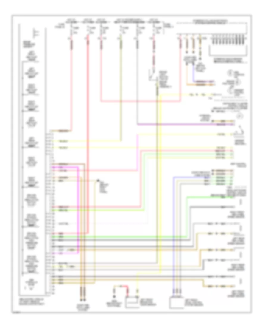
List of elements for Anti-lock Brakes Wiring Diagram for Audi A3 Quattro 2006:
- Abs control module (at right rear of engine compartment)
- Abs hydraulic pump
- Abs warning ind
- Asr/esp button
- Asr/esp control lamp
- Brake pad wear ind
- Brake pressure sensor 1
- C2 nca
- Computer data lines system
- Driving dynamic regulation high pressure switch valve 1
- Driving dynamic regulation high pressure switch valve 2
- Driving dynamic regulation switch valve 1
- Driving dynamic regulation switch valve 2
- Esp control module
- Fuse 10a
- Fuse 30a
- Fuse 5a
- Fuse panel b
- Fuse panel c
- G43 (behind right kick panel)
- G44 (behind left kick panel)
- G638 (behind right kick panel)
- Headlamp range control module (behind right center of dash)
- Hot at all times
- Instrument cluster control module (behind instrument cluster)
- Interior lights system
- Left front abs inlet valve
- Left front abs outlet valve
- Left front abs wheel speed sensor
- Left front brake pad wear sensor
- Left front level control system sensor
- Left rear abs inlet valve
- Left rear abs outlet valve
- Left rear abs wheel speed sensor
- Nca
- Red
- Right front abs inlet valve
- Right front abs outlet valve
- Right front abs wheel speed sensor
- Right rear abs inlet valve
- Right rear abs outlet valve
- Right rear abs wheel speed sensor
- Steering angle sensor (behind steering wheel)
- Steering column electronic systems control module
- T26a
- T32
 English