ANTI-LOCK BRAKES
Anti-lock Brakes Wiring Diagram (1 of 2) for Audi A6 Quattro Premium Plus 2014

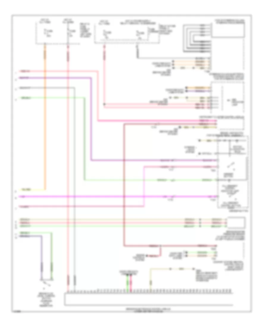
List of elements for Anti-lock Brakes Wiring Diagram (1 of 2) for Audi A6 Quattro Premium Plus 2014:
- 40a
- Abs control module (part of abs hydraulic unit)
- Abs control module fuse 1
- Abs hydraulic pump
- Abs hydraulic unit
- Auto hold button
- Computer data lines system
- Driver central locking lock unit
- Driver door control module (in driver front door)
- Driving dynamics regulation high pressure switch valve 1
- Driving dynamics regulation high pressure switch valve 2
- Driving dynamics regulation switch valve 1
- Driving dynamics regulation switch valve 2
- Electro-mechanical parking brake button
- Fuse 10a
- Fuse 5a
- Fuse carrier
- G55 (near abs control module)
- Hot at all times
- Left front abs inlet valve
- Left front abs outlet valve
- Left front abs wheel speed sensor (on left front wheel hub)
- Left rear abs inlet valve
- Left rear abs outlet valve
- Left rear abs wheel speed sensor (on left rear wheel hub)
- Main fuse carrier (in luggage compt on battery)
- Pnk
- Red
- Relay & fuse panel b (left end of dash)
- Right front abs inlet valve
- Right front abs outlet valve
- Right front abs wheel speed sensor (on right front wheel hub)
- Right rear abs inlet valve
- Right rear abs outlet valve
- Right rear abs wheel speed sensor (on right rear wheel hub)
- Safety fuse 3 150a
- T16c
- T17i
- T23a
- T32a
- Vehicle electrical system control module (left end of dash)
Anti-lock Brakes Wiring Diagram (2 of 2) for Audi A6 Quattro Premium Plus 2014
List of elements for Anti-lock Brakes Wiring Diagram (2 of 2) for Audi A6 Quattro Premium Plus 2014:
- (top of steering column) steering angle sensor
- Abs indicator lamp
- Asr/esp button
- Brake booster pressure sensor (w/ start/stop system) (in left plenum chamber)
- Brake fluid level warning switch (on brake fluid reservoir)
- Brake lamp switch (top of brake pedal assembly)
- Comfort system central control module (right side of luggage compt)
- Computer data lines system
- Engine controls system
- Fuse 20a
- Fuse 5a
- Fuse carrier
- G45 (behind center of dash)
- G688 (below rear seat, near data bus on board diagnostic interface)
- Hill descent control button (awd)
- Hill descent control indicator lamp (awd)
- Hot at all times
- Instrument cluster control module
- Interior lights system
- Nca
- Pnk
- Relay & fuse panel c (right end of dash)
- Relay & fuse panel d (under left side of dash)
- Sensor electronics control module (under center console)
- Steering column electronic systems control module (top of steering column)
- Switch illumination bulb
- T10k
- T16e
- T17i
- T17o
- T32g
- T32i
- T6ai