ANTI-LOCK BRAKES
4.2L
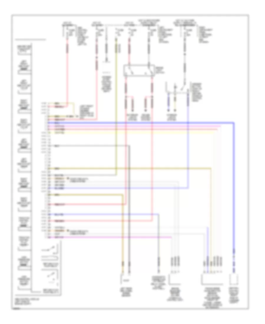
4.2L, Anti-lock Brakes Wiring Diagram for Audi A8 L Quattro 2007

List of elements for 4.2L, Anti-lock Brakes Wiring Diagram for Audi A8 L Quattro 2007:
- (left front chassis member, forward of front axle) g12
- 12a
- 22a
- 27a
- Abs control module (left side of engine compt)
- Abs control module fuse 1 (on relay & fuse panel, left i/p)
- Abs return flow pump
- Access/ start control module (under driver's seat)
- Asr/esp button (part of front/ center console control head)
- B19
- Brake booster sender 1 (on abs hydraulic control unit)
- Brake light switch
- Central control module (right side of luggage compt)
- Computer data lines system
- Cruise control system
- Diagnostic connection (at front relay panel, in left footwell)
- Exterior lights system
- Fuse 25a
- Fuse 5a
- Fuse 60a
- High pressure switch valve 1
- High pressure switch valve 2
- Hot at all times
- Interior lights system
- Left front abs inlet valve
- Left front abs outlet valve
- Left front abs wheel speed sensor
- Left instrument panel fuse panel (in left end of dash)
- Left rear abs inlet valve
- Left rear abs outlet valve
- Left rear abs wheel speed sensor
- Return flow pump relay
- Return flow pump relay 2
- Right front abs inlet valve
- Right front abs outlet valve
- Right front abs wheel speed sensor
- Right instrument panel fuse panel (in right end of dash)
- Right rear abs inlet valve
- Right rear abs outlet valve
- Right rear abs wheel speed sensor
- Traction control pilot valve 1
- Traction control pilot valve 2
- Transverse acceleration sensor/ rotation rate sender (on front of tunnel, under center console extension)
6.0L
6.0L, Anti-lock Brakes Wiring Diagram for Audi A8 L Quattro 2007
List of elements for 6.0L, Anti-lock Brakes Wiring Diagram for Audi A8 L Quattro 2007:
- (left front chassis member, forward of front axle) g12
- 12a
- 22a
- 27a
- Abs control module (left side of engine compt)
- Abs control module fuse 1 (on relay & fuse panel, left i/p)
- Abs return flow pump
- Access/ start control module (under driver's seat)
- Asr/esp button (part of front/ center console control head)
- B19
- Brake booster sender (on abs hydraulic control unit)
- Brake light switch
- Central control module (right side of luggage compt)
- Computer data lines system
- Cruise control system
- Diagnostic connection (at front relay panel, in left footwell)
- Exterior lights system
- Fuse 25a
- Fuse 5a
- Fuse 60a
- High pressure switch valve 1
- High pressure switch valve 2
- Hot at all times
- Interior lights system
- Left front abs inlet valve
- Left front abs outlet valve
- Left instrument panel fuse panel (in left end of dash)
- Left rear abs inlet valve
- Left rear abs outlet valve
- Left rear abs wheel speed sensor
- Return flow pump relay
- Return flow pump relay 2
- Right front abs inlet valve
- Right front abs outlet valve
- Right instrument panel fuse panel (in right end of dash)
- Right rear abs inlet valve
- Right rear abs outlet valve
- Traction control pilot valve 1
- Traction control pilot valve 2
- Transverse acceleration sensor/ rotation rate sender (front of tunnel, under center console extension)