ANTI-LOCK BRAKES
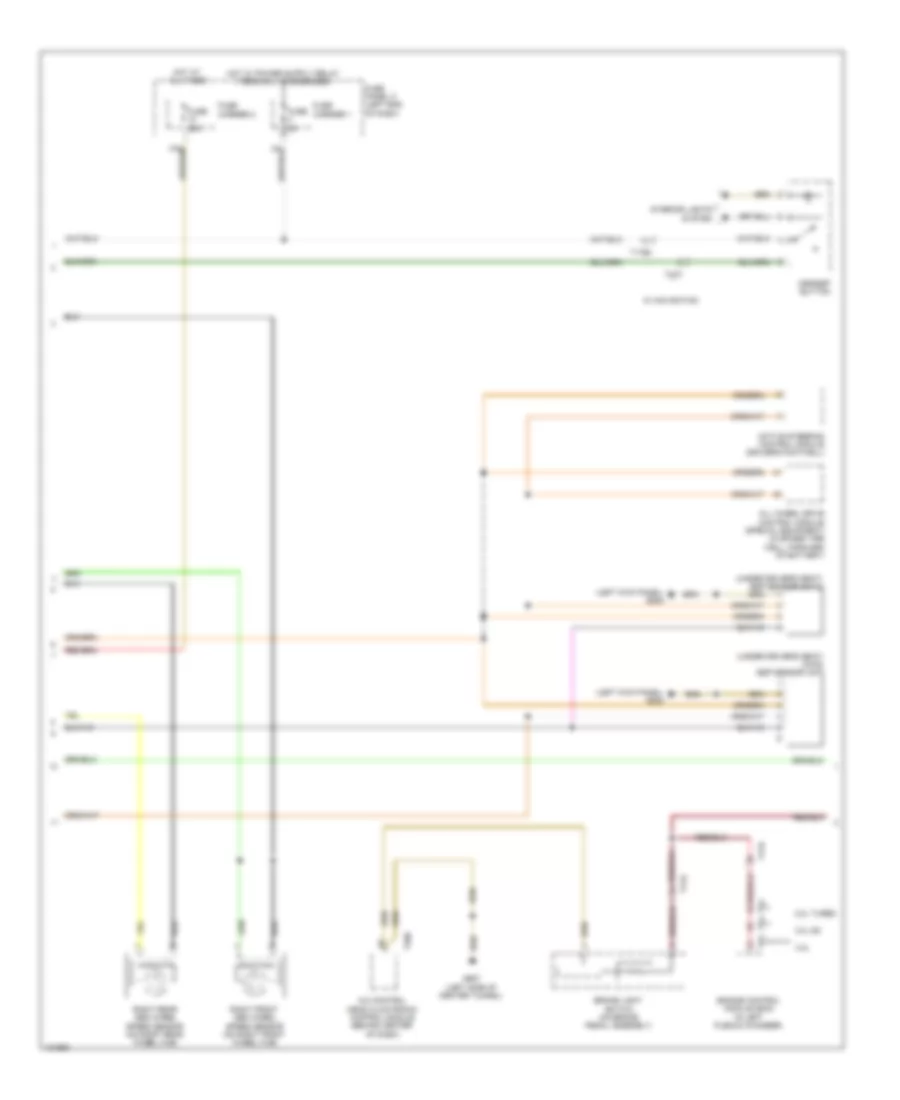
Anti-lock Brakes Wiring Diagram (1 of 3) for Audi RS 5 Cabriolet 2014

List of elements for Anti-lock Brakes Wiring Diagram (1 of 3) for Audi RS 5 Cabriolet 2014:
- (left side of engine compt) abs control module
- (not used)
- (on left front cross member) g671
- 40a
- Abs control module fuse 1
- Abs hydraulic unit
- Abs inlet left rear
- Abs outlet left rear
- Auto hold button
- Computer data lines system
- Convertible
- Driving dynamics regulation high pressure switch valve 2
- Electro-mechanical parking brake button
- Fuse 10a
- Fuse 110a
- Fuse carrier 2
- Fuse panel a (on battery, in luggage compt)
- Fuse panel c (left end of dash)
- G671 (on left front cross member)
- Hot at all times
- Left front abs inlet valve
- Left front abs outlet valve
- Left front abs wheel speed sensor (on left front wheel hub)
- Left rear abs wheel speed sensor (on left rear wheel hub)
- Red
- Regulation high driving dynamics
- Regulation switch driving dynamics
- Right front abs inlet valve
- Right front abs outlet valve
- Right rear abs inlet valve
- Right rear abs outlet valve
- T10m
- T10p
- T17d
- Valve
- Valve 1
- Valve 1 pressure switch
- Valve 2
Anti-lock Brakes Wiring Diagram (2 of 3) for Audi RS 5 Cabriolet 2014
List of elements for Anti-lock Brakes Wiring Diagram (2 of 3) for Audi RS 5 Cabriolet 2014:
- (left kick panel) g639
- (under driver's seat) (awd) esp sensor unit
- (under driver's seat) esp sensor unit 2
- 2.0l turbo
- 3.0l sc
- 4.2l
- A/c control head climatronic control module (behind center of dash)
- Active steering control module (driver's footwell)
- All wheel drive control module (special equipment) (in spare tire well, forward of battery)
- Asr/esp button
- Brake light switch (on brake pedal assembly)
- Engine control module (ecm) (in left plenum chamber)
- Fuse 25a
- Fuse 5a
- Fuse carrier 1
- Fuse carrier 2
- Fuse panel c (left end of dash)
- G687 (left side of center tunnel)
- Hot at all times
- Interior lights system
- Right front abs wheel speed sensor (on right front wheel hub)
- Right rear abs wheel speed sensor (on right rear wheel hub)
- T17c
- T17e
- T17r
- T20e
- T91
- T94
- W/ navigation
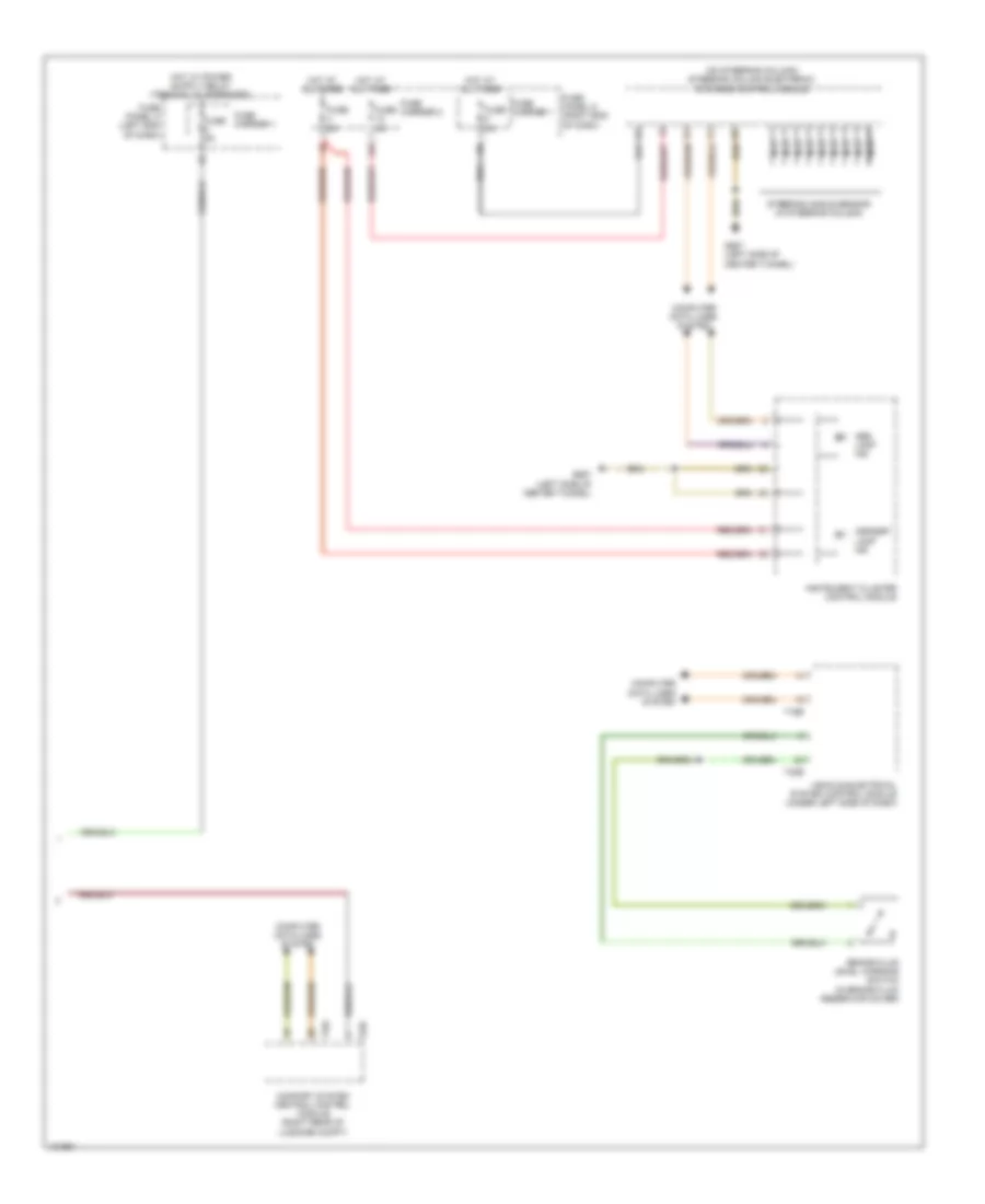
Anti-lock Brakes Wiring Diagram (3 of 3) for Audi RS 5 Cabriolet 2014
List of elements for Anti-lock Brakes Wiring Diagram (3 of 3) for Audi RS 5 Cabriolet 2014:
- (on steering column) steering column electronic systems control module
- 12a
- Abs lamp ind
- Asr/esp lamp ind
- Brake fluid level warning switch (in brake fluid reservoir cover)
- Comfort system central control module (right rear of luggage compt)
- Computer data lines system
- Fuse 5a
- Fuse carrier 1
- Fuse carrier 2
- Fuse panel c (left end of dash)
- Fuse panel d (right end of dash)
- G687 (left side of center tunnel)
- Hot at all times
- Instrument cluster control module
- Nca
- Steering angle sensor (in steering column)
- T16b
- T32b
- T32c
- T32d
- Vehicle electrical system control module (under left side of dash)