ANTI-LOCK BRAKES
Anti-lock Brakes Wiring Diagram for Audi TTS Premium Plus 2013
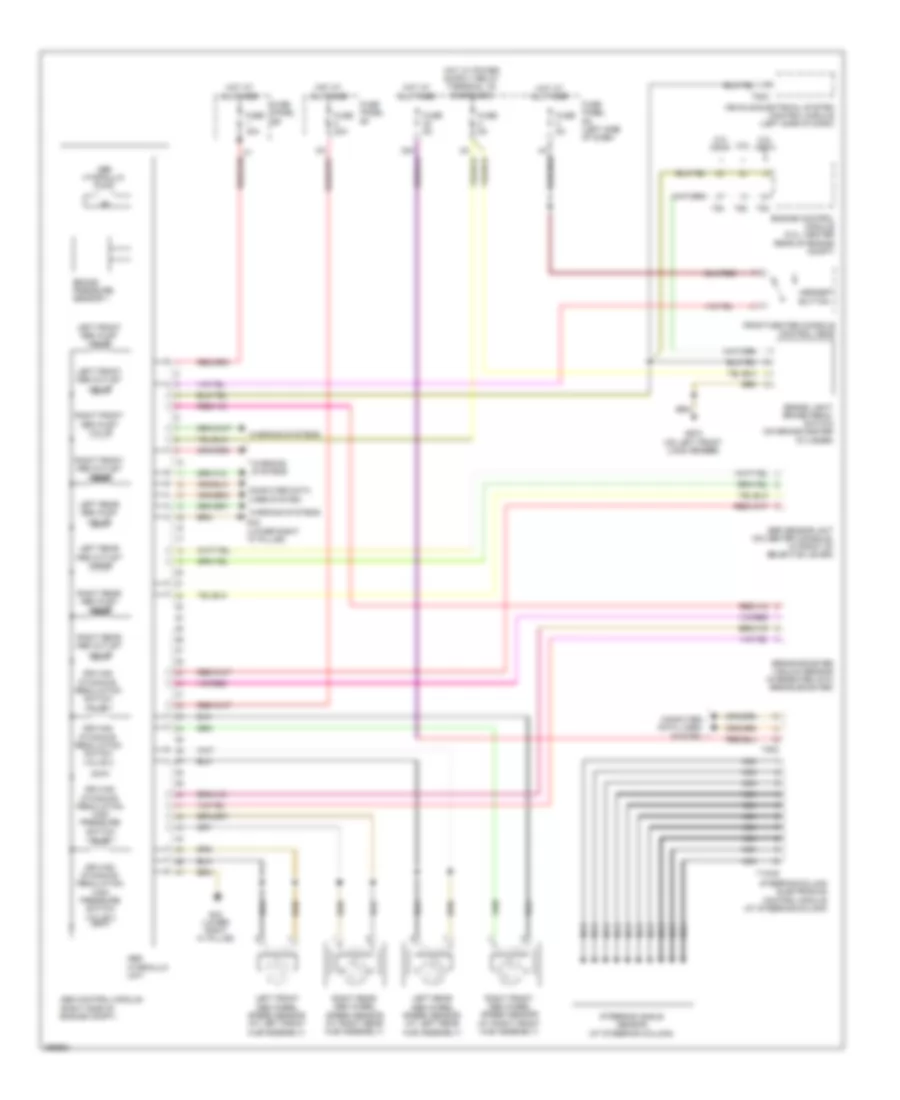
List of elements for Anti-lock Brakes Wiring Diagram for Audi TTS Premium Plus 2013:
- 2.0l cdma
- 2.0l ceta
- 2.5l
- 32a
- Abs control module (right side of engine compt)
- Abs hydraulic pump
- Abs hydraulic unit
- Asr/esp button
- Brake booster vacuum sensor (integrated into brake booster)
- Brake light/ brake pedal switch (on brake master cylinder)
- Brake pressure sensor 1
- Computer data lines system
- Driving dynamics regulation high pressure switch valve 1
- Driving dynamics regulation high pressure switch valve 2
- Driving dynamics regulation switch valve 1
- Driving dynamics regulation switch valve 2
- Engine control module (2.0l: center rear of engine compt)
- Esp sensor unit (on center console, in front of selector lever)
- Front/center console control head
- Fuse 20a
- Fuse 40a
- Fuse 5a
- Fuse panel sc (left side of dash)
- Fuse panel sd
- Fuse panel sf
- G43 (lower right "a" pillar)
- G672 (on left front long member)
- Hot at all times
- Left front abs inlet valve
- Left front abs outlet valve
- Left front abs wheel speed sensor (at left front hub assembly)
- Left rear abs inlet valve
- Left rear abs outlet valve
- Left rear abs wheel speed sensor (at left rear hub assembly)
- Nca
- Right front abs inlet valve
- Right front abs outlet valve
- Right front abs wheel speed sensor (at right front hub assembly)
- Right rear abs inlet valve
- Right rear abs outlet valve
- Right rear abs wheel speed sensor (at right rear hub assembly)
- Steering angle sensor (at steering column)
- Steering column electronics control module (at steering column)
- T10ag
- T20c
- T52c
- T60
- T94
- Vehicle electrical system control module (left side of dash)
- Warning systems
 English