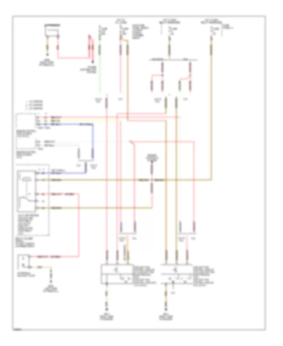
COOLING FAN
Cooling Fan Wiring Diagram for Audi S6 Quattro 2008
List of elements for Cooling Fan Wiring Diagram for Audi S6 Quattro 2008:
- (or red)
- 3.2l
- 3.2l engine
- 4.2l & 5.2l
- 4.2l engine
- 5.2l engine
- After-run coolant pump
- Auxiliary engine coolant (ec) pump relay (3.2l & 5.2l) coolant circulation pump relay (4.2l)
- Coolant fan control module (w/ coolant fan electronics) (3.2l) coolant fan control module 2 (4.2l & 5.2l)
- Coolant fan control module (w/o coolant fan electronics) (3.2l) coolant fan control module (4.2l & 5.2l)
- Engine control module (ecm) (3.2l)
- Engine control module (ecm) (4.2l & 5.2l)
- Engine controls system
- Fuse 5a
- Fuse 60a
- Fuse panel a
- G614 (right side of engine)
- G645 (left side of firewall)
- G646 (right side of firewall)
- Hot at all times
- Hot w/ ecm relay energized
- Main fuse panel (e-box) (in right plenum chamber e-box)
- Power distribution system
- Red
- Relay holder (e-box) (in left plenum chamber e-box)
- Suppressor
- T94a
 English