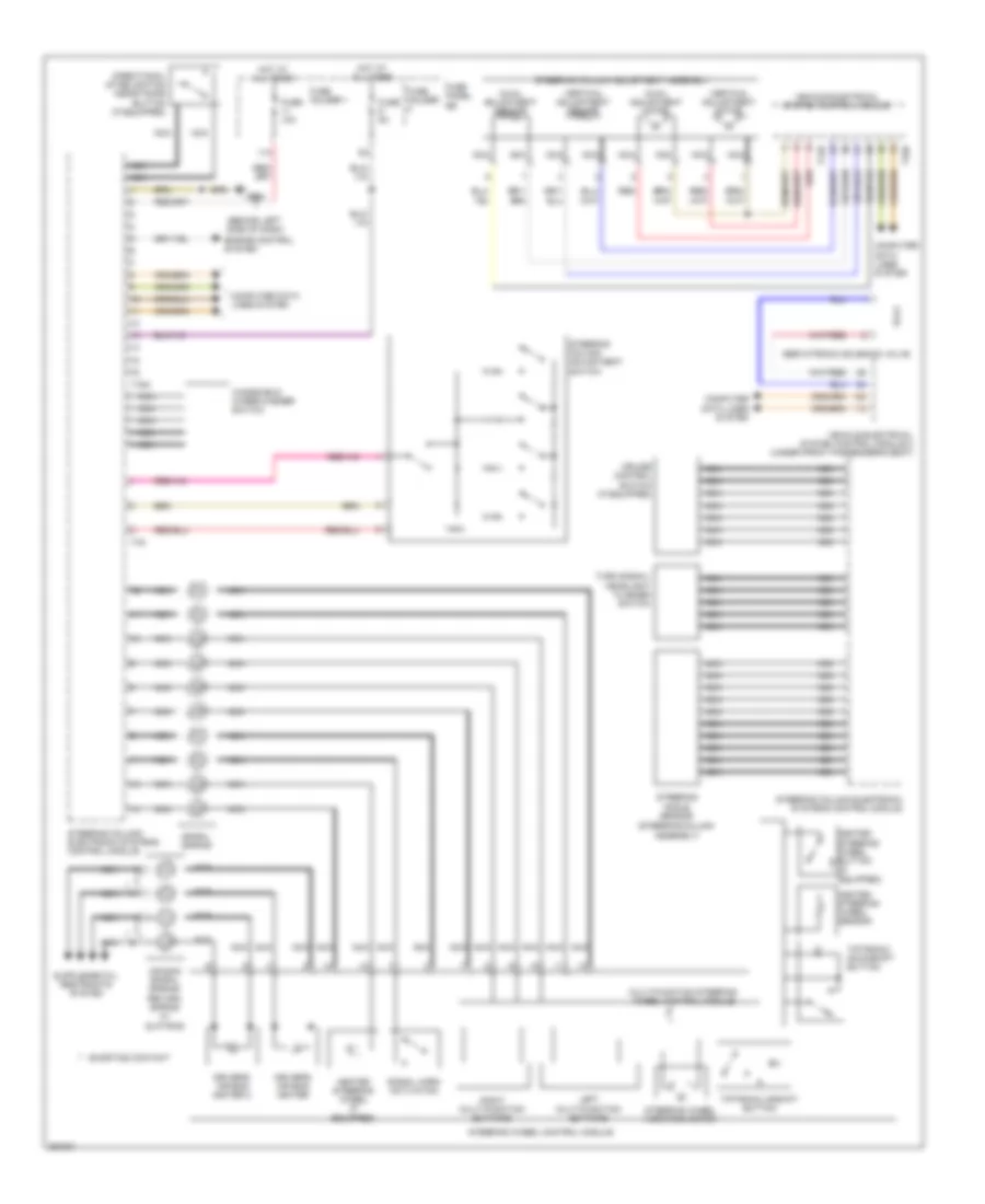
ELECTRONIC POWER STEERING
Electronic Power Steering Wiring Diagram for Audi Q7 3.0 TDI 2011
List of elements for Electronic Power Steering Wiring Diagram for Audi Q7 3.0 TDI 2011:
- (behind left side of dash)
- (steering column assembly)
- 11a
- Air bag spiral spring/ return spring w/ slip ring
- Axial adjustment motor
- Axial adjustment sensor
- Computer data lines system
- Cruise control switch (if equipped)
- Directional stabilization assistance button (if equipped)
- Driver's air bag igniter
- Driver's air bag igniter 2
- Engine control system
- Fuse 10a
- Fuse 5a
- Fuse holder
- Fuse holder 1
- Fuse panel sb
- G664
- Heated steering wheel (if equipped)
- Heated steering wheel button (if equipped)
- Heated steering wheel sensor
- Hot at all times
- Left multi-function buttons
- Multi-function steering wheel control module
- Nca
- Red
- Right multi-function buttons
- Servotronic solenoid valve
- Shorting contact
- Signal horn activation
- Spiral spring
- Steering angle sensor
- Steering column adjustment assembly
- Steering column adjustment switch
- Steering column electronic systems control module
- Steering wheel control module
- Steering wheel vibration motor
- T12b
- T16a
- T32b
- T4a
- Tiptronic downshift button
- Tiptronic upshift button
- Turn signal/ headlight flasher switch
- Vehicle electrical system control module
- Vehicle electrical system control module 2 (under front passenger's seat)
- Vertical adjustment motor
- Vertical adjustment sensor
- Windshield wiper/washer switch
 English