ENGINE PERFORMANCE
4.2L
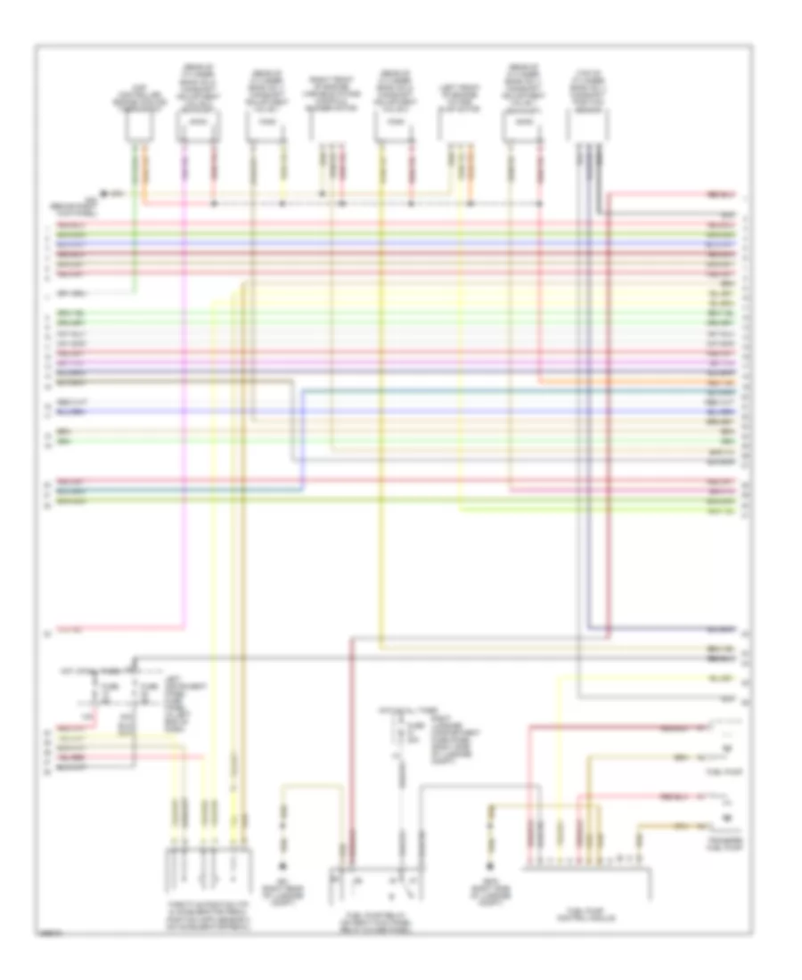
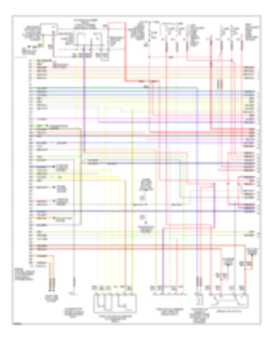
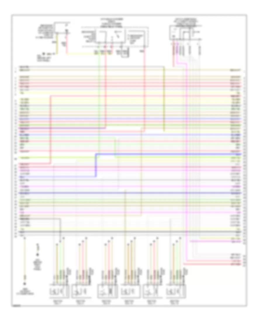
4.2L, Engine Performance Wiring Diagram (1 of 5) for Audi A8 L Quattro 2007

List of elements for 4.2L, Engine Performance Wiring Diagram (1 of 5) for Audi A8 L Quattro 2007:
- (rear of cylinder bank no 2) camshaft position sensor 4
- (rear of cylinder bank no. 1) mass air flow (maf) sensor
- (top of cylinder bank no 2) camshaft position sensor 2
- (top of cylinder bank no 2) low fuel pressure sensor
- Anti-lock brakes system
- Anti-theft system starting/ charging system
- Brake booster pressure sensor
- Brake pedal switch
- Comfort system central control module
- Cooling fans system
- Cruise control system
- Engine control module (ecm) (in passenger's side plenum chamber e-box)
- Fuse 5a
- G43 (behind right kick panel)
- G44 (behind left kick panel)
- Heated oxygen sensor (downstream of right 3-way catalytic converter)
- Heated oxygen sensor 2 (upstream of left 3-way catalytic converter)
- Heated oxygen sensor 2 behind 3-way catalytic converter (twc) (downstream of left 3-way catalytic converter)
- Heated oxygen sensor behind 3-way catalytic converter (twc) (downstream of right 3-way catalytic converter)
- Kick down switch (under accelerator pedal)
- Nca
- Partial
- Right instrument panel fuse panel (in right end of dash)
- Starting/ charging system
- T10q
- T94
- Transmissions system
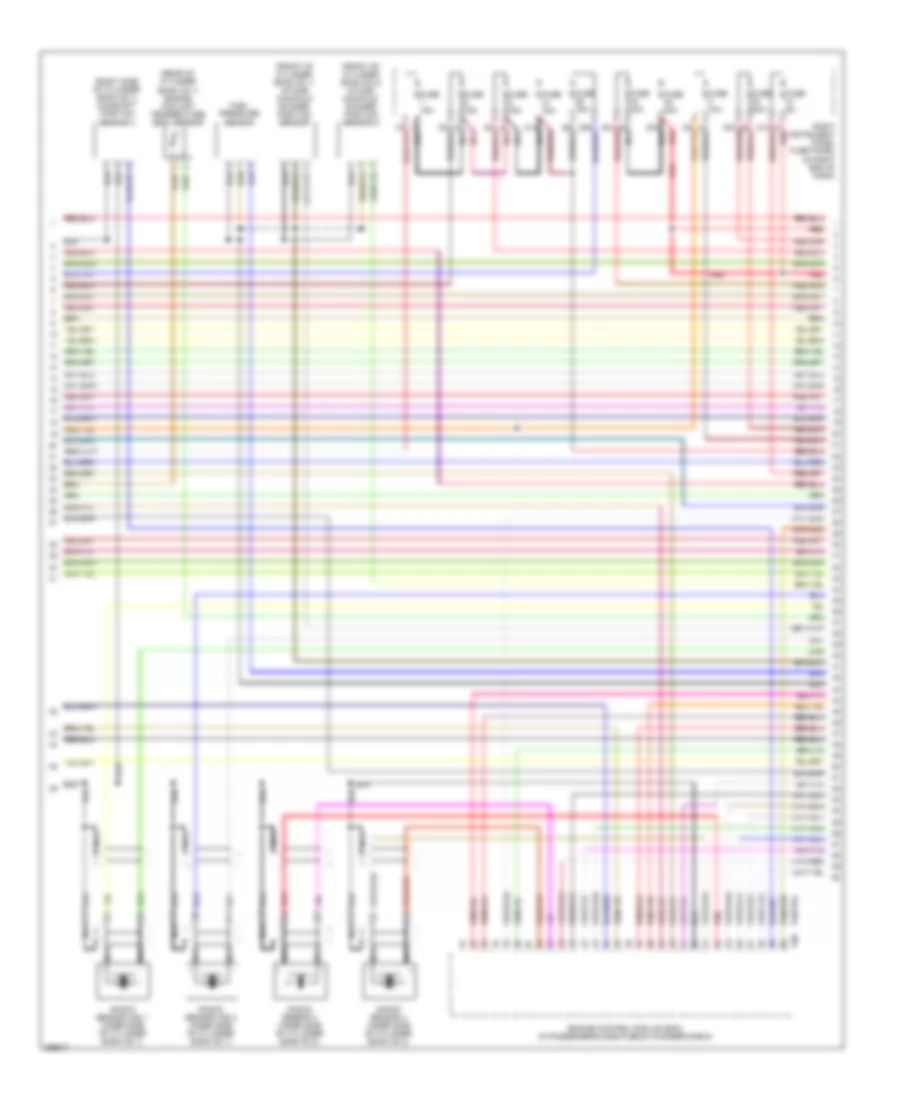
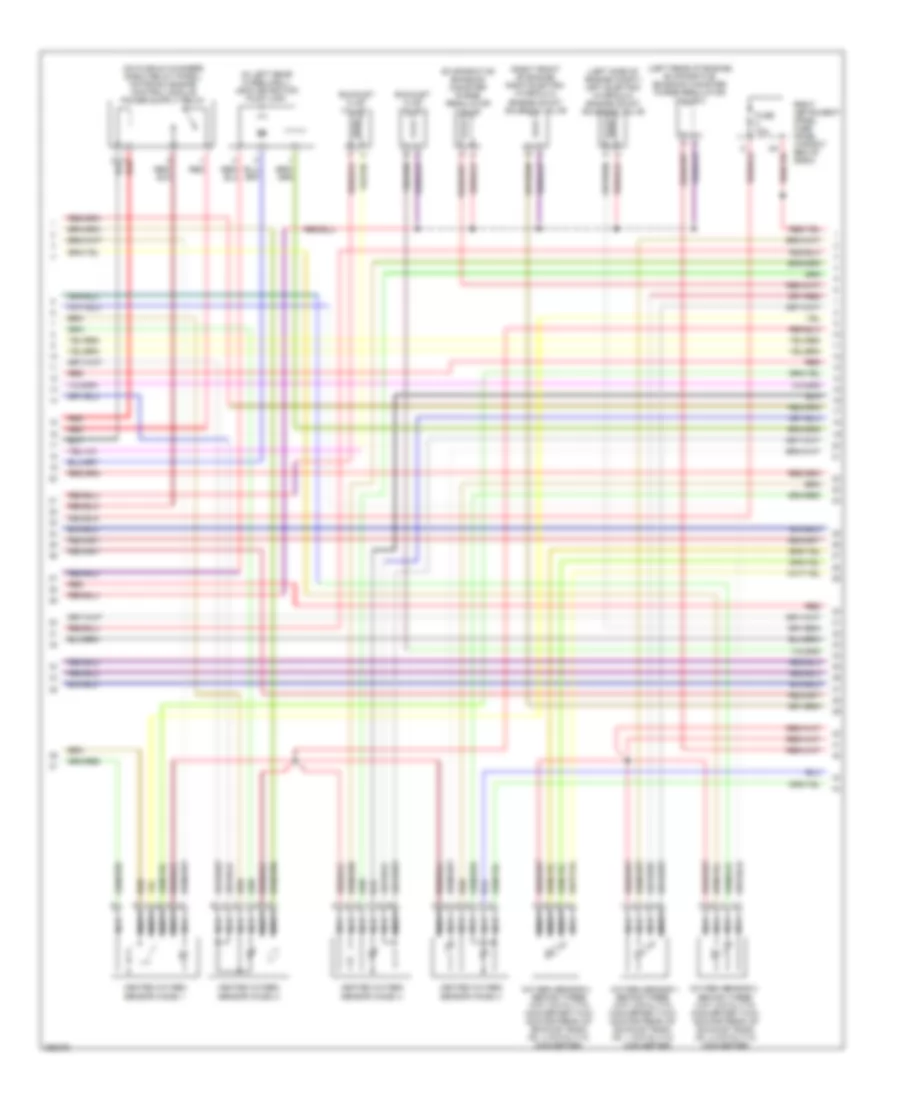
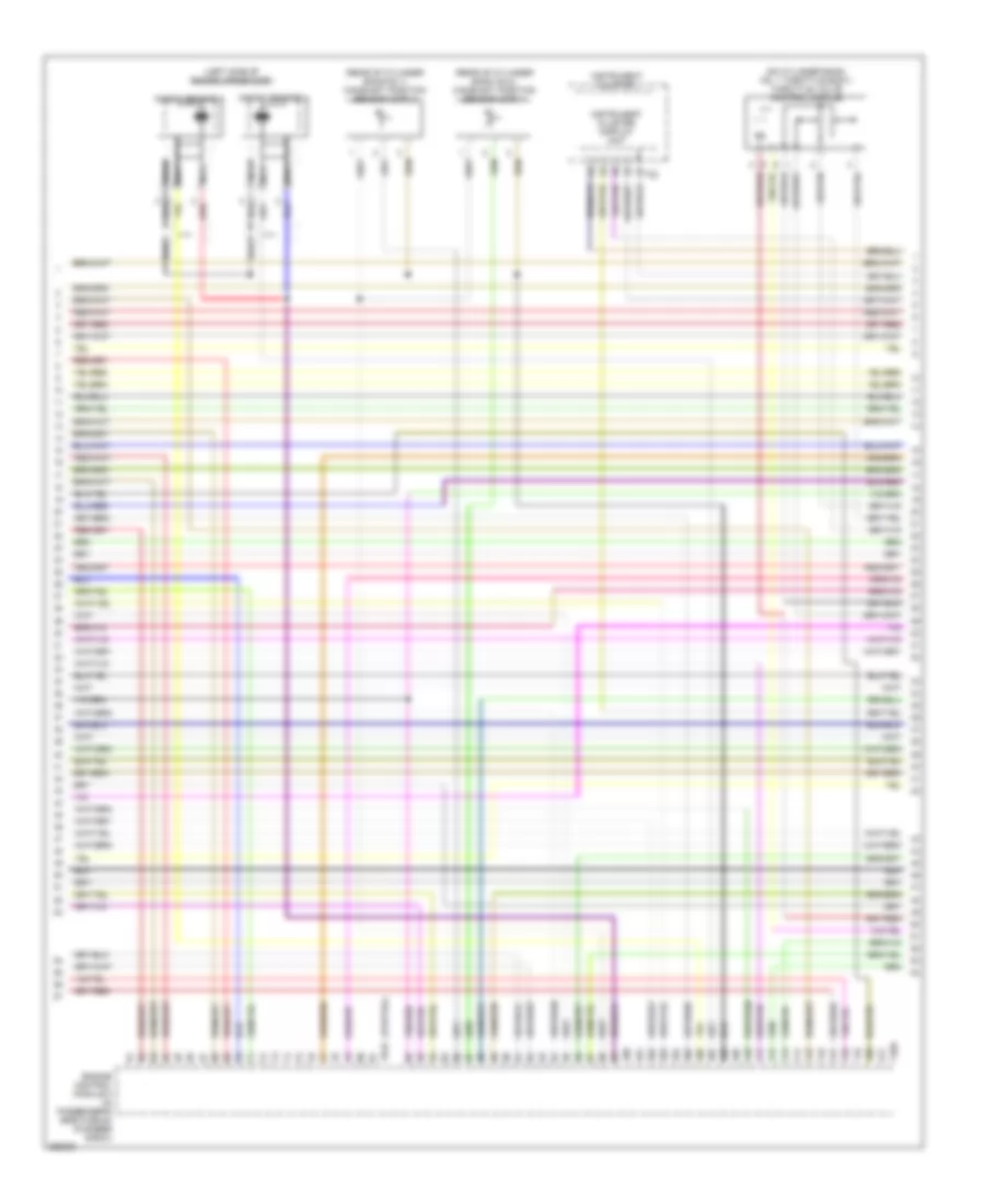
4.2L, Engine Performance Wiring Diagram (2 of 5) for Audi A8 L Quattro 2007
List of elements for 4.2L, Engine Performance Wiring Diagram (2 of 5) for Audi A8 L Quattro 2007:
- (left front of engine) intake flap motor
- (rear of cylinder bank no 1) camshaft adjustment valve 1
- (rear of cylinder bank no 1) camshaft adjustment valve 1 (exhaust)
- (rear of cylinder bank no 2) camshaft adjustment valve 2
- (rear of cylinder bank no 2) camshaft adjustment valve 2 (exhaust)
- (right front of engine) variable intake manifold runner motor
- (top of cylinder bank no 1) camshaft position sensor
- 12a
- 22a
- Fuel pump
- Fuel pump control module
- Fuel pump relay (on right kick panel relay & fuse panel)
- Fuse 40a
- Fuse 5a
- G43 (behind right kick panel)
- G51 (right rear of luggage compt)
- G675 (right side of luggage compt)
- Hot at all times
- Left instrument panel fuse panel (in left end of dash)
- Map controlled engine cooling thermostat
- Right luggage compartment fuse panel (right side of luggage compt)
- Throttle position (tp) & accelerator pedal position (app) sensor 2 (on accelerator pedal)
- Transfer fuel pump
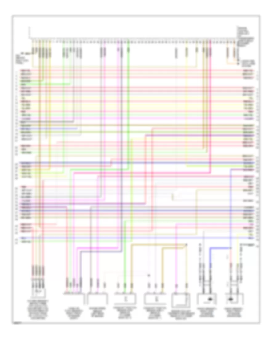
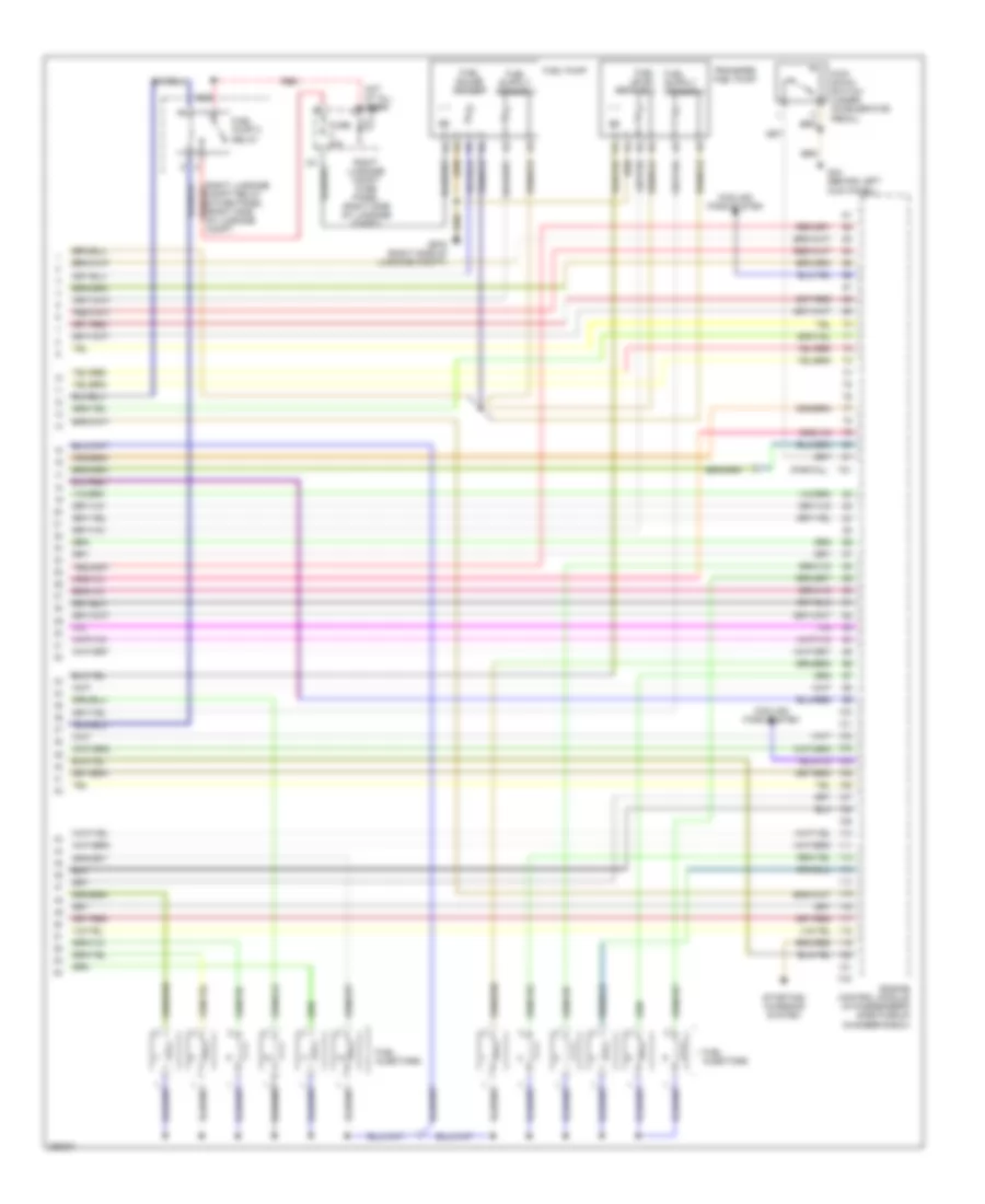
4.2L, Engine Performance Wiring Diagram (3 of 5) for Audi A8 L Quattro 2007
List of elements for 4.2L, Engine Performance Wiring Diagram (3 of 5) for Audi A8 L Quattro 2007:
- (front of cylinder bank no 1) intake manifold runner position sensor
- (front of cylinder bank no 2) intake manifold runner position sensor 2
- (rear of cylinder bank no 1) engine coolant temperature (ect) sensor
- (right side of cylinder bank no 1) camshaft position sensor 3
- 31a nca
- 38a nca
- Engine control module (ecm) (in passenger's side plenum chamber e-box)
- Fuel pressure sensor
- Fuse 10a
- Fuse 15a
- Fuse 30a
- Fuse 40a
- Fuse 5a
- Knock sensor (ks) 1 (inner side of cylinder bank no 1)
- Knock sensor (ks) 2 (inner side of cylinder bank no 1)
- Knock sensor 3 (inner side of cylinder bank no 2)
- Knock sensor 4 (inner side of cylinder bank no 2)
- Nca
- Partial
- Red
- Right instrument panel fuse panel (in right end of dash)
- T60
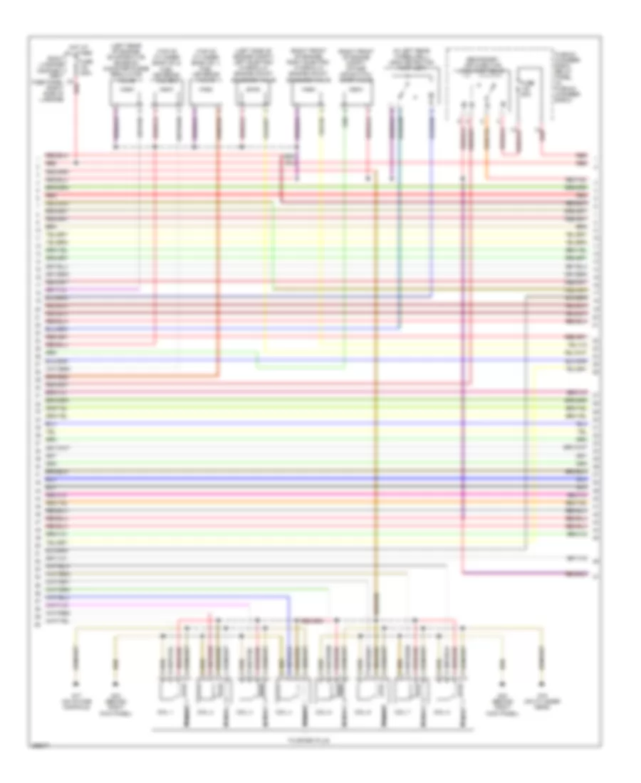
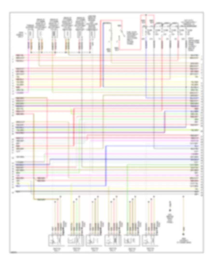
4.2L, Engine Performance Wiring Diagram (4 of 5) for Audi A8 L Quattro 2007
List of elements for 4.2L, Engine Performance Wiring Diagram (4 of 5) for Audi A8 L Quattro 2007:
- (in left rear wheelwell) leak detection pump (ldp)
- (left rear of engine) evaporative emission canister purge regulator valve
- (left side of engine compt) left electro- hydraulic engine mount solenoid valve
- (right front of engine compt) intake air switch- over valve
- (right front of engine) right electro- hydraulic engine mount solenoid valve
- (top of cylinder bank no 1) fuel metering valve
- (top of cylinder bank no 2) fuel metering valve 2
- 1a red
- 3a red
- Coil 1
- Coil 2
- Coil 3
- Coil 4
- Coil 5
- Coil 6
- Coil 7
- Coil 8
- Fuse 150a
- Fuse 50a
- G15 (on cylinder head)
- G17 (on intake manifold)
- G43 (behind right kick panel)
- Hot at all times
- Nca
- Plenum chamber e-box relay panel (in plenum chamber e-box)
- Red
- Right luggage compart- ment fuse panel (right side of luggage
- Secondary air injection (air) pump relay
- To spark plug
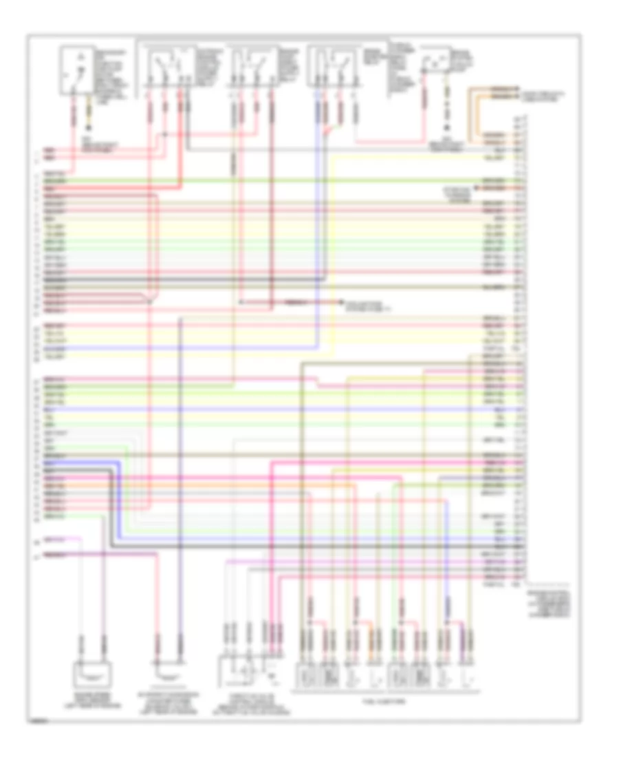
4.2L, Engine Performance Wiring Diagram (5 of 5) for Audi A8 L Quattro 2007
List of elements for 4.2L, Engine Performance Wiring Diagram (5 of 5) for Audi A8 L Quattro 2007:
- Brake booster relay
- Brake system vacuum pump
- Computer data lines system
- Cooling fans system (fuse 17)
- Engine control module (ecm) (in passenger's side plenum chamber e-box)
- Engine speed (rpm) sensor (left rear of engine)
- Evaporative emission canister purge solenoid valve 2 (left rear of engine)
- Fuel injectors
- G43 (behind right kick panel)
- Partial
- Plenum chamber e-box relay panel (in plenum chamber e-box)
- Red
- Secondary air injection (air) pump motor (between right front bumper & wheelwell line)
- Starting/ charging system
- T60
- T94
- Throttle valve control module (behind intake manifold, on throttle valve housing)
6.0L
6.0L, Engine Performance Wiring Diagram (1 of 7) for Audi A8 L Quattro 2007
List of elements for 6.0L, Engine Performance Wiring Diagram (1 of 7) for Audi A8 L Quattro 2007:
- (in plenum chamber e-box) plenum chamber e-box relay panel
- (partial)
- (under left side of dash) data link connector
- 12a
- 22a
- 3a red
- A17
- Access/start control module (under driver's seat)
- Anti-lock brakes system
- Brake light switch
- Computer data lines system
- Cooling fans system
- Cruise control system
- Engine control module (in passenger's side plenum chamber e-box)
- Evaporative emission canister purge solenoid valve (left rear of engine)
- Exterior lights system
- Fuse 150a
- Fuse 30a
- Fuse 5a
- G43 (behind right kick panel)
- G44 (behind left kick panel)
- Hot at all times
- Left instrument panel fuse panel (behind left side of dash)
- Mass air flow sensor (left front of engine compt)
- Red
- Right instrument panel fuse panel (right end of dash)
- Right luggage compartment fuse panel (right side of luggage compt)
- Secondary air injection pump motor (in lower part of air filter housing)
- Secondary air injection pump relay
- Secondary air pump fuse 50a
- Starting/ charging system
- T81
- Throttle position sensor (on accelerator pedal)
- Transmission controls system
- Transmissions system
6.0L, Engine Performance Wiring Diagram (2 of 7) for Audi A8 L Quattro 2007
List of elements for 6.0L, Engine Performance Wiring Diagram (2 of 7) for Audi A8 L Quattro 2007:
- (in left rear wheelwell) leak detection pump (ldp)
- (left rear of engine) evaporative emission canister purge regulator valve 2
- (left side of engine compt) left electro- hydraulic engine mount solenoid valve
- (right front of engine) right electro- hydraulic engine mount solenoid valve
- Behind three way catalytic converter (twc) (downstream of exhaust bank no. 2 catalytic converter)
- Converter)
- Evaporative emission canister purge regulator valve
- Exhaust flap valve 1
- Exhaust flap valve 2
- Fuse 10a
- Heated oxygen sensor (ho2s) 1
- Heated oxygen sensor (ho2s) 2
- Heated oxygen sensor (ho2s) 3
- Heated oxygen sensor (ho2s) 4
- Nca
- Oxygen sensor 1 behind three way catalytic converter (twc) (downstream of exhaust bank no. 1 catalytic
- Oxygen sensor 2
- Oxygen sensor 4 behind three way catalytic converter (twc) (downstream of exhaust bank no. 4 catalytic converter)
- Red
- Right instrument panel fuse panel (in right end of dash)
6.0L, Engine Performance Wiring Diagram (3 of 7) for Audi A8 L Quattro 2007
List of elements for 6.0L, Engine Performance Wiring Diagram (3 of 7) for Audi A8 L Quattro 2007:
- (partial)
- Camshaft position sensor (cmp) (rear of cylinder bank no. 2)
- Camshaft position sensor (cmp) 3 (rear of cylinder bank no. 1)
- Computer data lines system
- Engine control module 2 (in passenger's side plenum t81a chamber e-box)
- Engine coolant temperature sensor (rear of cylinder bank no)
- Engine speed sensor (left rear of engine)
- G43 (behind right kick panel)
- Knock sensor 1 (right front of engine crankcase)
- Knock sensor 2 (right side of engine crankcase)
- Mass air flow sensor 2 (right front of engine compt)
- Nca
- Oxygen sensor 3 behind three way catalytic converter (twc) (downstream of exhaust bank no. 3 catalytic converter)
- Red
6.0L, Engine Performance Wiring Diagram (4 of 7) for Audi A8 L Quattro 2007
List of elements for 6.0L, Engine Performance Wiring Diagram (4 of 7) for Audi A8 L Quattro 2007:
- (2006 models only)
- (center rear of engine) map controlled engine cooling thermostat
- (rear of cylinder bank no. 1) camshaft adjustment valve 1
- (rear of cylinder bank no. 1) camshaft adjustment valve 1 (exhaust)
- (rear of cylinder bank no. 2) camshaft adjustment valve 2
- (rear of cylinder bank no. 2) camshaft adjustment valve 2 (exhaust)
- 28a
- 29a
- 31a
- Fuel pump pump relay (on right kick panel relay & fuse panel)
- Fuse 15a
- Fuse 20a
- Fuse 5a
- G43 (behind right kick panel)
- G600 (on right cylinder head)
- Ignition coil 1
- Ignition coil 2
- Ignition coil 3
- Ignition coil 4
- Ignition coil 5
- Ignition coil 6
- Nca
- Plug spark
- Red
- Right instrument panel fuse panel (in right end of dash)
- Spark plug
- Torque support valve
6.0L, Engine Performance Wiring Diagram (5 of 7) for Audi A8 L Quattro 2007
List of elements for 6.0L, Engine Performance Wiring Diagram (5 of 7) for Audi A8 L Quattro 2007:
- (in plenum chamber e-box) plenum chamber e-box relay panel
- (on cylinder bank no. 2 throttle body) throttle valve control module 2
- G43 (behind right kick panel)
- G44 (behind left kick panel)
- G600 (on right cylinder head)
- Ignition coil 10
- Ignition coil 11
- Ignition coil 12
- Ignition coil 7
- Ignition coil 8
- Ignition coil 9
- Nca
- Plug spark
- Red
- Secondary air injection pump motor 2 (in lower air part of filter housing)
- Secondary air injection pump relay 2
- Secondary air pump fuse 50a
- Spark plug
6.0L, Engine Performance Wiring Diagram (6 of 7) for Audi A8 L Quattro 2007
List of elements for 6.0L, Engine Performance Wiring Diagram (6 of 7) for Audi A8 L Quattro 2007:
- (left side of engine crankcase)
- (on cylinder bank no. 1 throttle body) throttle valve control module
- (partial)
- (rear of cylinder bank no.1) camshaft position sensor (cmp) 2
- (rear of cylinder bank no.2) camshaft position sensor (cmp) 4
- Engine control module 2 (in passenger's side plenum chamber e-box)
- Instrument cluster
- Instrument cluster display unit
- Knock sensor 3
- Knock sensor 4
- Nca
- Red
- T32
- T40a
- T81a
6.0L, Engine Performance Wiring Diagram (7 of 7) for Audi A8 L Quattro 2007
List of elements for 6.0L, Engine Performance Wiring Diagram (7 of 7) for Audi A8 L Quattro 2007:
- (partial)
- Compt relay & fuse panel (right side of luggage compt
- Cooling fans system
- Engine control module (in passenger's side plenum chamber e-box)
- Fuel gauge sender
- Fuel injectors
- Fuel level sensor 2
- Fuel pump
- Fuel pump 2 relay
- Fuse 20a
- G44 (behind left kick panel)
- G675 (right side of luggage compt)
- Hot at all times
- Kick down switch (under accelerator pedal)
- Red
- Right luggage compt fuse panel (right side of luggage compt)
- Starting/ charging system
- T40
- T81
- Transfer fuel pump