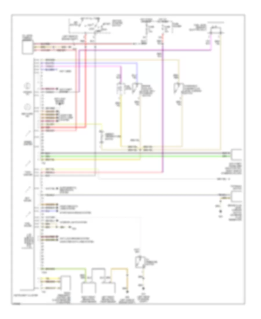
INSTRUMENT CLUSTER
Instrument Cluster Wiring Diagram for Audi RS 4 2007
List of elements for Instrument Cluster Wiring Diagram for Audi RS 4 2007:
- (left rear of engine compt)
- (left side of engine compt)
- (not used)
- 15a
- Acc
- Air bag mil
- Ambient temperature switch
- Anti-lock brakes system
- Anti-theft immobilizer induction coil (right side of steering column)
- Anti-theft system
- Brake fluid level warning switch (on brake fluid reservoir)
- Computer data lines system
- Ect gauge
- Engine coolant level (ecl) warning switch
- Fuel gauge
- Fuel level
- Fuel level sensor 2 (quattro only)
- Fuse 10a
- Fuse holder
- G12
- G26
- G33
- Gen warn ind
- Hot at all times
- Hot in run or start
- Ignition/ starter switch
- Instrument cluster
- Interior lights system
- Key switch
- Left front brake pad wear sensor
- Lock
- Off
- Oil level thermal sensor
- Oil pressure switch
- Radio frequency controlled clock
- Radio frequency controlled clock receiver (if equipped)
- Red
- Right front brake pad wear sensor
- Run
- Speed- ometer
- Start
- Starting/charging system
- T32
- T32a
- T4m
- Tach- ometer
- Tiptronic switch
- Windshield washer fluid level warning switch
 English