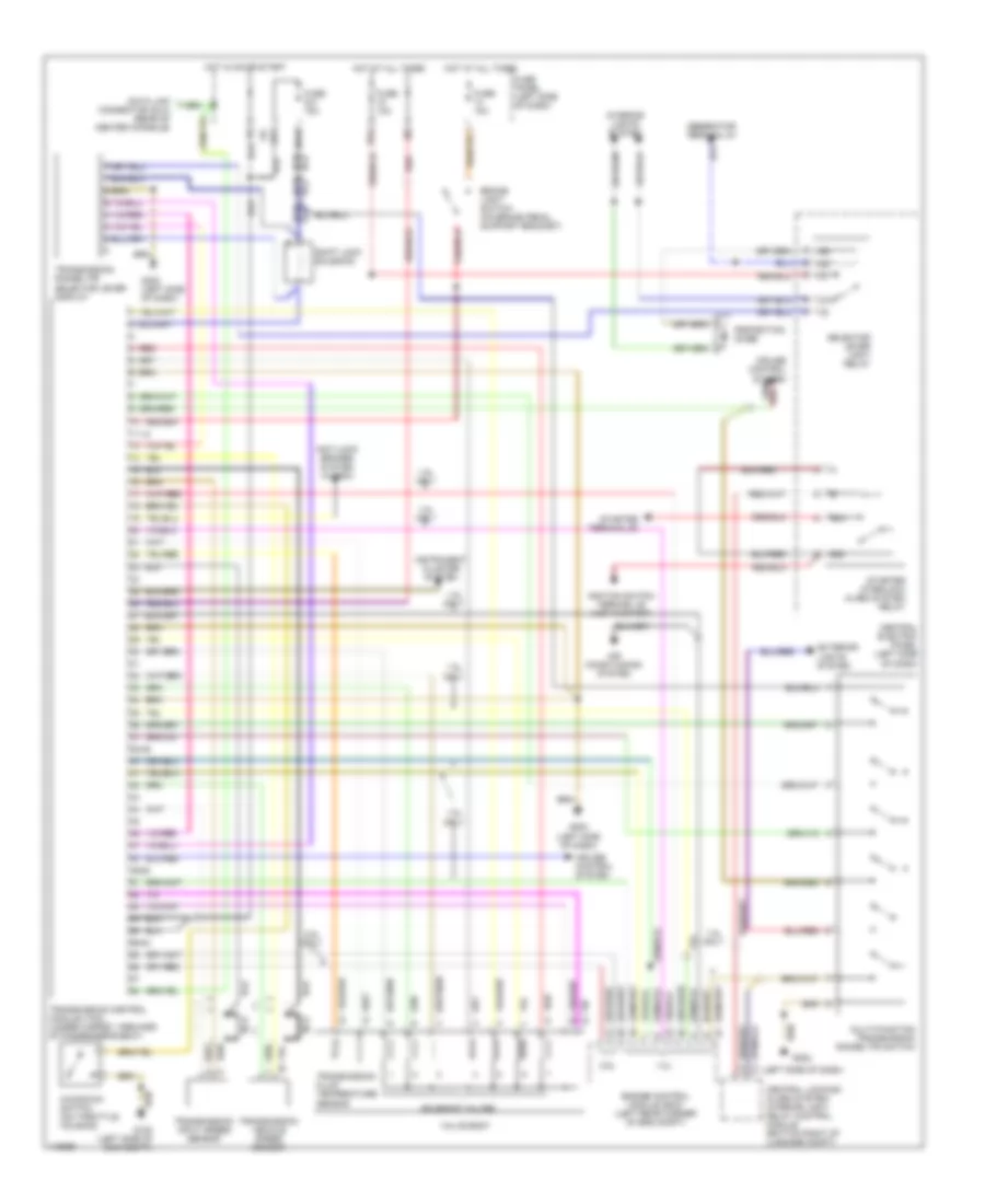
TRANSMISSION
A/T Wiring Diagram for Audi A4 Avant 1998
List of elements for A/T Wiring Diagram for Audi A4 Avant 1998:
- (left side of dash)
- 1.8l
- 1.8l only
- 11-12
- 15a
- 2.8l
- 2.8l only
- 231a
- 38-39
- 49-50
- 50a
- 50z
- 56-84
- 87a
- Air conditioning system
- Anti-lock brakes system (w/ asc)
- Brake light switch (on brake pedal support bracket)
- Central electric panel (left side of dash)
- Central locking/ alarm system/ interior light delay control module (bottom right of luggage compt)
- Cruise control system
- Data link connector (dlc) (rear of center console)
- Engine control module (ecm) (left rear corner of eng compt)
- Exterior lights system
- Fuse 10a
- Fuse 15a
- Fuse panel (left side of dash)
- G102 (left side of eng compt)
- G202
- G202 (left side of dash)
- Generator terminal d+
- Hot at all times
- Hot in on or start
- Ignition switch terminal 50 (hot in start)
- Instrument cluster system
- Interior lights system
- Kickdown switch (on throttle housing)
- Multi-function transmission range (tr) switch
- Nca
- Protection diode
- Red
- Selector lever light relay
- Shift lock solenoid
- Solenoid valves
- Starter interlock alarm system relay
- Starter terminal 50
- Transmission control module (tcm) (under carpet, forward of passenger's seat)
- Transmission fluid temperature sensor
- Transmission input speed sensor
- Transmission range (tr) selector lever display
- Transmission vehicle speed sensor
- Valve body
 English