TRANSMISSION
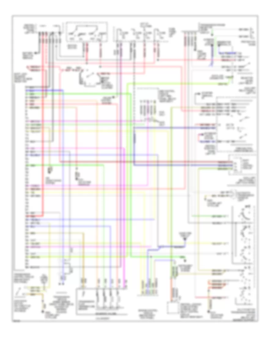
A/T Wiring Diagram for Audi A6 1995
List of elements for A/T Wiring Diagram for Audi A6 1995:
- 14a
- 15a
- 20a
- 50a
- 50z
- 87a
- Abs control module (left heel
- Acc
- Acc on
- Air conditioning system
- All wheel drive only
- Automatic transmission console light
- Auxiliary relay panel 1 (left i/p)
- Auxilliary relay panel 2 (left kick panel)
- Awd only
- B10
- B11
- B12
- B13
- Battery positive terminal
- Brake light switch (on pedal cluster)
- Central electric panel (left i/p)
- Central locking/ alarm system/ interior light delay control module (below rear seat)
- Computer display unit
- Cruise control system
- Data link connector
- Engine control module (behind right kick panel)
- Exterior lights system
- Fuse 10a
- Fuse 15a
- Fuse 5a
- Fuse panel (left i/p)
- Fwd only
- G131 (on intake manifold)
- G200 (lower left "a" pillar)
- G900 (lower left "a" pillar)
- Generator terminal d+
- Hot at all times
- Ignition switch
- Instrument cluster system
- Interior lights system
- Kick down switch (on throttle valve body, or cable)
- Multi-function transmission range
- Mv1
- Mv2
- Mv3
- Nca
- Not used
- Off
- P/n
- Panel, below rear seat)
- Park/neutral position relay
- Protection diode
- Red
- Red/
- Selector lever light relay
- Shift lock control module
- Shift lock solenoid (front of gear selector)
- Solenoid valves
- Start
- Starter terminal
- Switch (below left gearbox support)
- T16
- Transmission control module (behind right kick panel)
- Transmission fluid temperature sensor
- Transmission range selector lever display
- Transmission vehicle speed sensor (front wheel drive) (on right of gearbox housing)
- Valve body
 English