WARNING SYSTEMS
Warning Systems Wiring Diagram for Audi 90 Sport 1995
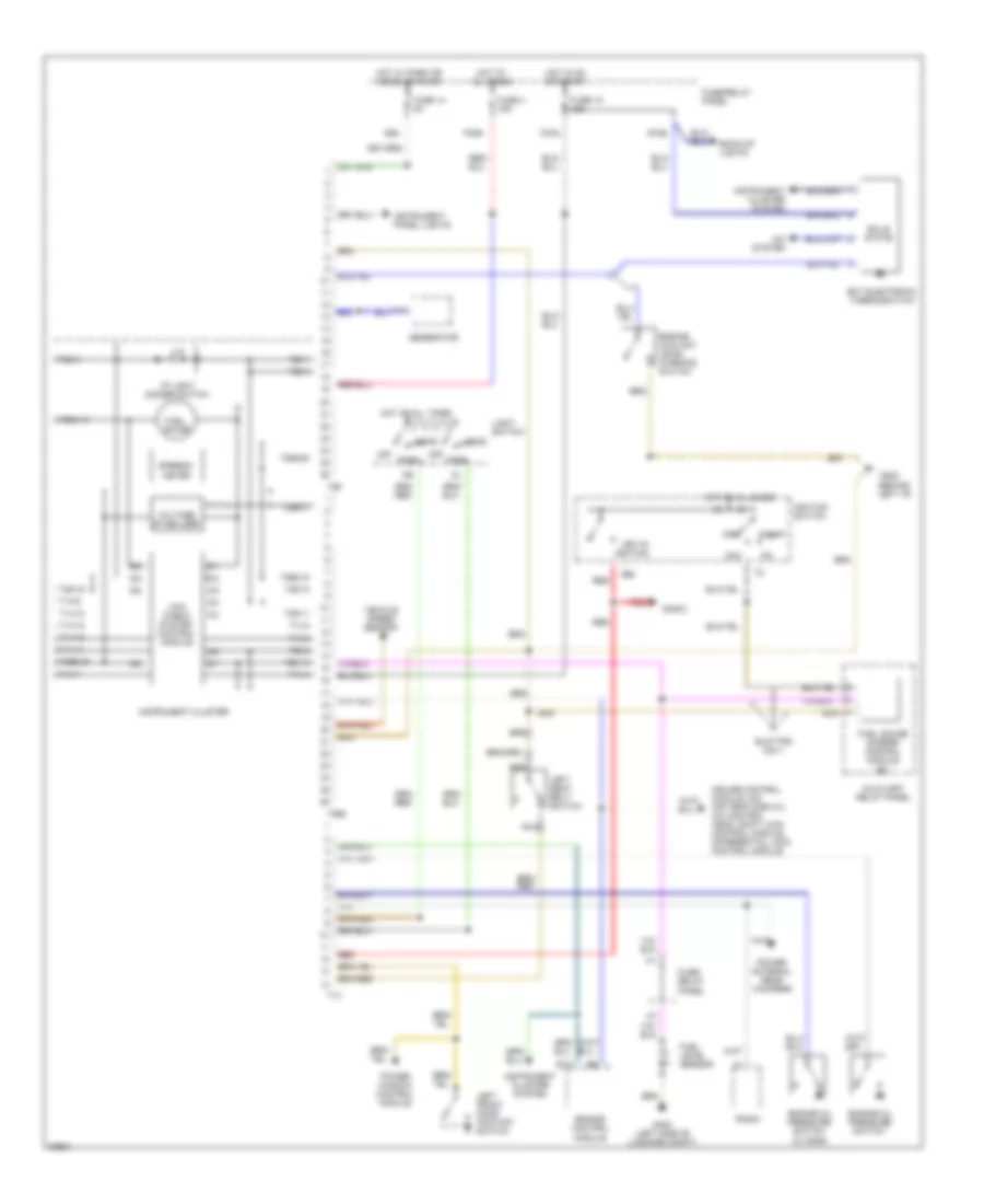
List of elements for Warning Systems Wiring Diagram for Audi 90 Sport 1995:
- (0.3 bar)
- (behind left i/p)
- 5/1
- 5/2
- 5/3
- 5/4
- 5/5
- 6/1
- 6/2
- 6/3
- 6/4
- 6/5
- 6/6
- 86s
- A/c system
- Acc
- Auxiliary relay panel
- B10
- B15a
- Back-up lights
- C15a
- Cruise control module, o/s air temp display, a/c control head, shift lock control module, differential lock control module
- Ect electronic thermoswitch
- Engine control module
- Engine coolant level warning switch
- Engine oil pressure switch
- F30al
- Fuel gauge
- Fuel gauge damper control module (#7)
- Fuel level sensor
- Fuse 12 15a
- Fuse 14 5a
- Fuse 4 15a
- Fuse/ relay panel
- Fuse/relay panel
- G202
- G402 (left side of luggage compt)
- Generator
- Head
- Hot at all times
- Hot in on or start
- Hot w/ park or headlights on
- I/p light dimmer switch
- I58d
- Ignition switch
- Instrument cluster
- Instrument cluster system
- Instrument panel lights
- Key-in ignition
- Left front door contact switch
- Left seat belt switch
- Light switch
- Mini- check system control module
- Nca
- Off
- Park
- Power antenna, rear woofers
- Power window control module
- Quattro only
- Radio
- Red
- Solid state
- Speedo- meter
- Start
- T14
- T14-10
- T14-12
- T14-13
- T14-14
- T14-3
- T14-4
- T14-7
- T14-8
- T14-9
- T26
- T26-1
- T26-10
- T26-11
- T26-13
- T26-19
- T26-4
- T26-5
- T26-8
- T26a
- T26a-15
- T26a-16
- T26a-18
- T26a-20
- T26a-21
- Vehicle speed sensor
- Voltage stabilizer
 English