WARNING SYSTEMS
Brake Wear Sensor Wiring Diagram for Audi A5 Quattro 2009

List of elements for Brake Wear Sensor Wiring Diagram for Audi A5 Quattro 2009:
- Computer data lines system
- Discontinued (phased in modification)
- Fuse 7 30a 20a
- Fuse carrier
- Fuse panel sc (under left side of dash)
- G639 (behind left kick panel)
- Hot at all times
- Instrument cluster control module
- Left front brake pad wear sensor
- Phased in modification
- T16b
- T17l
- T17m
- T32b
- Vehicle electrical system control module (on relay & fuse panel)
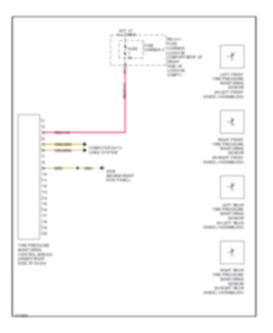
Tire Pressure Monitoring Wiring Diagram for Audi A5 Quattro 2009
List of elements for Tire Pressure Monitoring Wiring Diagram for Audi A5 Quattro 2009:
- (in left front wheel assemblies)
- (in left rear wheel assemblies)
- (in right front wheel assemblies)
- Computer data lines system
- Fuse 5a
- Fuse carrier 2
- G638 (behind right kick panel)
- Hot at all times
- Left front tire pressure monitoring sensor
- Left rear tire pressure monitoring sensor
- Relay/ fuse carrier luggage compartment sf (right side of luggage compt)
- Right front tire pressure monitoring sensor
- Right rear tire pressure monitoring sensor (in right rear wheel assemblies)
- Tire pressure monitoring control module (under right side of dash)