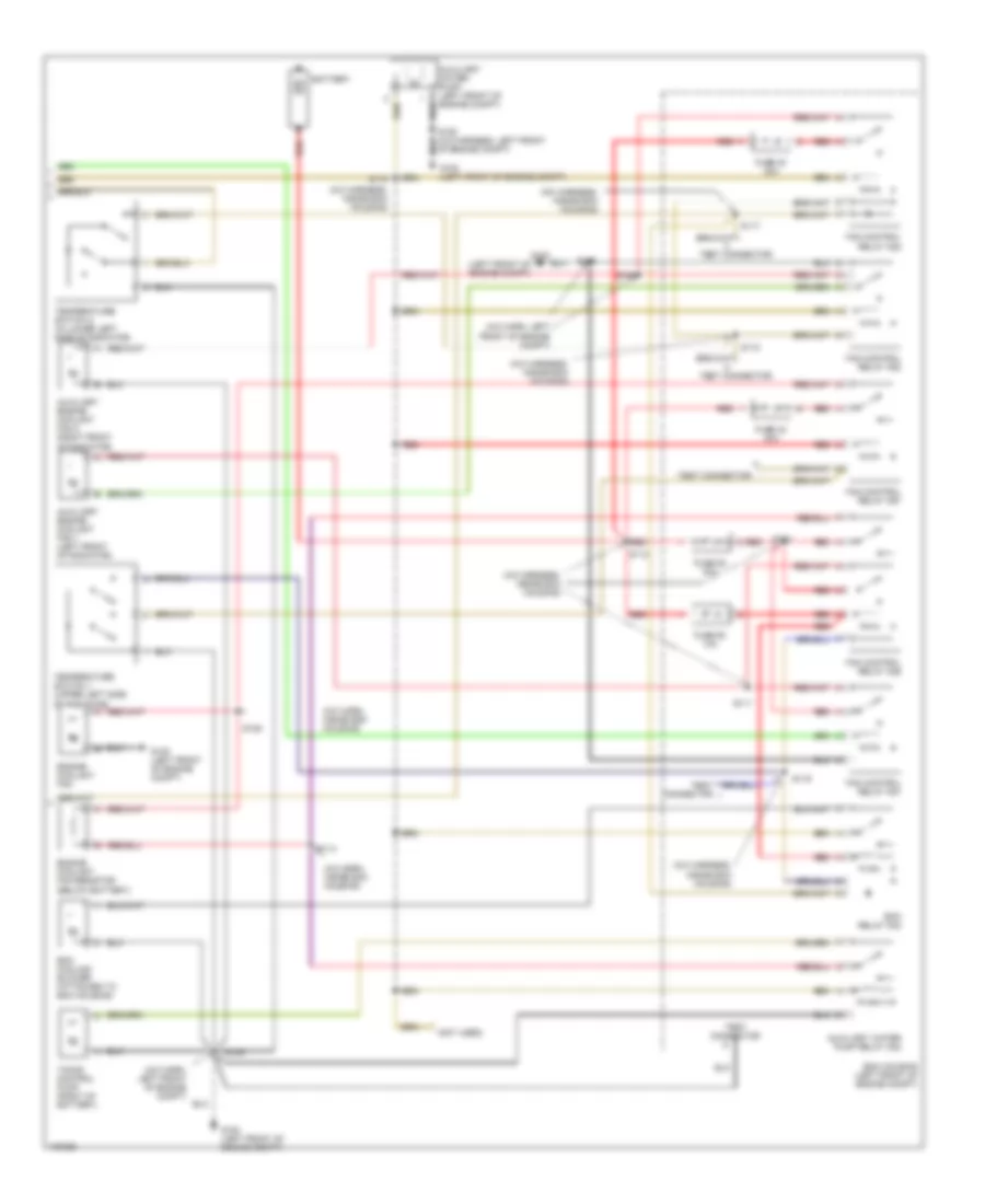
AIR CONDITIONING
A/C Wiring Diagram (1 of 2) for Cadillac Catera 1998

List of elements for A/C Wiring Diagram (1 of 2) for Cadillac Catera 1998:
- (a/c harn, in ecm housing)
- (a/c harn, left front of engine compt)
- (a/c harn, rear of hvac module)
- (i/p harn, near break- out to dlc)
- (i/p harn, near dlc breakout)
- (i/p harn, right side of dash)
- (i/p harness, near cluster breakout)
- (i/p harness, near dlc breakout)
- (left front of engine compt)
- (left front of engine compt) g100
- (left side of dash) data link connector
- +5v
- A/c compressor clutch coil
- A/c compressor diode
- A/c compressor refrigerant pressure switch (left front of engine compt)
- A/c compressor relay
- A/c control switch (left front of engine compt)
- A/c cutout
- A/c req
- A/c req out
- A/c request
- A11
- A400
- Air mix 1
- Air mix 2
- Air mix 3
- Air mix 4
- Ambient air outside temperature sensor
- Blower controller (right side of dash)
- Blower diag
- Blower motor
- Blower out
- Body control module (on right "a" pillar)
- Bp900
- Cig fuse 14 20a
- Clamp 15a fuse 10 10a
- Clamp 56 fuse 26 10a
- Day/night sig
- Def 1
- Def 2
- Def 3
- Def 4
- Defog sw
- Defogger system
- Defroster valve actuator (right side of dash)
- Ecm housing (left front of engine compt)
- Electronic brake/ traction control module (left front of engine compt)
- Engine control module
- Engine controls system
- F800
- F830
- Floor 1
- Floor 2
- Floor 3
- Floor 4
- Fm11
- Fm14
- Fm430
- Fm60
- Fm8
- Fp120
- Fp812
- Fuse block
- G100
- Ground
- Headlamp automatic control ambient light sensor (top of dash)
- Headlights system
- Heater and a/c control
- Heater and a/c recirc vacuum solenoid valve (behind right side of dash)
- Heater and a/c water vacuum solenoid valve (behind right side of dash)
- Heater blower fuse 33 30a
- Hot at all times
- Hot in run
- Hot in run, bulb test or start
- Hzd fuse 12 20a
- Ign volt
- Inside air valve actuator (right side of dash)
- Int dim
- Interior lights system
- Left air duct temperature sensor (behind right side of dash)
- Left temperature valve actuator (right side of dash)
- Mode valve actuator (right side of dash)
- O/s mirror fuse 13 10a
- Outside temp
- P11
- P111
- Pa400
- Pa900
- Pm4
- Power
- Rb400
- Recirc valve
- Red
- Relay ctrl
- Right air duct temperature sensor (behind right side of dash)
- Right temperature valve actuator (right side of dash)
- Ru502
- S110
- S160
- S205
- S211
- S215
- S220
- S229
- S235
- S236
- Sens gnd
- Sens left
- Sens right
- Serial data
- Speed sig
- Sun sens
- Tach input
- Test connector (in ecm housing)
- Trans- mission controls system
- Twilight sens
- U10
- Vent 1
- Vent 2
- Vent 3
- Vent 4
- Water vlv
- X800
- X812
- Xm110
- Xm112
- Xp33
- Xy360
A/C Wiring Diagram (2 of 2) for Cadillac Catera 1998
List of elements for A/C Wiring Diagram (2 of 2) for Cadillac Catera 1998:
- (a/c harn, inside ecm housing)
- (a/c harn, left front of engine compt)
- (a/c harness, inside ecm housing)
- (left front of engine compt)
- (not used)
- Auxiliary engine coolant fan 1 (left front of radiator)
- Auxiliary engine coolant fan 2 (right front of radiator)
- Auxiliary water pump (left front of engine compt)
- Auxiliary water pump relay k22
- Battery
- Ecm cooling blower (attached to ecm housing)
- Ecm housing (left front of engine compt)
- Ecm relay k48
- Engine coolant fan
- Engine coolant fan resistor (below battery)
- Fan control relay k26
- Fan control relay k28
- Fan control relay k52
- Fan control relay k67
- Fan control relay k87
- Fuse 40 30a
- Fuse 42 40a
- Fuse 50 10a
- Fuse 52 30a
- G100
- G100 (left front of engine compt)
- Of engine compt)
- Red
- S108
- S109
- S111
- S112
- S113
- S114
- S115
- S116
- S117
- S118
- S125
- Temperature switch 1 (upper left side of radiator)
- Temperature switch 2 (in lower left side of radiator)
- Test connector
- Timing control pump (right of battery)
- Y red
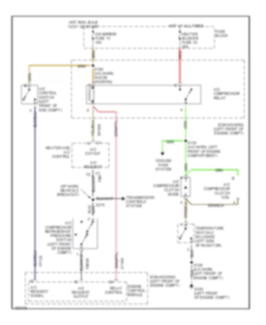
Compressor Wiring Diagram for Cadillac Catera 1998
List of elements for Compressor Wiring Diagram for Cadillac Catera 1998:
- (i/p harn, near dlc breakout)
- A/c compressor clutch coil
- A/c compressor clutch diode
- A/c compressor refrigerant pressure switch (left front of engine compt)
- A/c compressor relay
- A/c control switch (left front of eng compt)
- A/c cutout
- A/c request
- A/c request output
- A/c request signal
- Bp900
- C1 fm8
- Cooling fans system
- Ecm housing (left front of engine compt)
- Engine control module
- Fm340
- Fp120
- Fuse block
- G100 (left front of engine compt)
- Heater and a/c control
- Heater blower fuse 33 20a
- Hot at all times
- Hot run, bulb test or start
- O/s mirror fuse 13 10a
- Red
- Relay control
- S110 (a/c harn, left front of engine compartment)
- S160 (a/c harn, in ecm housing)
- Temperature switch 2 (in lower left side of radiator)
- Transmission controls system
- Xy360