AIR CONDITIONING
Automatic A/C Wiring Diagram (1 of 2) for Cadillac DTS 2006

List of elements for Automatic A/C Wiring Diagram (1 of 2) for Cadillac DTS 2006:
- (in body harness, approximately 14 cm (6 in) from breakout to yaw & lateral acceleration sensor) s301
- (in hvac harness, between evaporator temperature sensor & c202)
- (in hvac harness, between hvac control module & mode motors)
- (in i/p harness, approximately 36 cm (14 in) from breakout to hvac module) s203
- (in i/p harness, approximately 41 cm (16 in) from branch to hazard lamp switch)
- (lower right side of hvac module) blower motor
- (under driver's seat) g300
- 5 volt ref
- Air temp mtr ctrl
- Amb air temp sens ctrl
- Ambient air temperature sensor (forward of radiator)
- Asp
- Auxiliary mode actuator (bottom of hvac module, near auxiliary blower motor)
- Backlight lamp ctrl
- Batt
- Batt volt
- Blower motor control module
- Blw mtr lo ref
- Blw mtr spd ctrl
- Body harn mdl fuse 10a
- Cold
- Computer data lines system
- Def
- Defogger system
- Driver air temperature actuator (on left side of hvac module)
- Drv air temp dr ctrl a
- Drv air temp dr ctrl b
- Drv air temp dr pos sig
- Evap lo temp sens ig
- Evaporative temperature sensor (bottom of hvac module, near blower motor)
- Front passenger air temperature actuator (on right side of hvac module)
- Frt hvac blwr relay
- G300 (under driver's seat)
- G304 (under front passenger's seat)
- Gmlan serial data
- Gnd
- Hi blr mtr rly ctrl
- Hot
- Hot at all times
- Hot at at times
- Hot on run or start
- Hvac blwr fuse 40a
- Hvac control module
- I/p harn mdl fuse 10a
- Ign 1 volt
- Inside air temp sns sig
- Inside air temperature sensor (left of steering wheel)
- Interior lights system
- Led dimming sig
- Left sunload sens sig
- Logic
- Low mode dr pos sig
- Low ref
- Lower mode dr ctrl b
- Message center
- Message req
- Mode actuator (front center hvac module)
- Mode dr ctrl a
- Mtr spd ctrl
- Pas air temp dr ctrl a
- Pas air temp dr ctrl b
- Pas air temp dr pos
- Pnk
- Radio
- Rear air temp dr ctrl a
- Rear air temp dr pos
- Rear defog rly ctrl
- Rear fuse block (under left rear seat)
- Rear hvac fuse 5a
- Rear mode dr ctrl a
- Rear mode dr ctrl b
- Rear mode dr pos sig
- Rear passenger air temperature actuator (if equipped) (lower right side of hvac module)
- Recir dr ctrl a
- Recir dr ctrl b
- Recir vlv sol sig
- Recirculation actuator (right side of hvac module, above blower motor)
- Right sunload sens sig
- S203 (in i/p harness, approximately 36 cm (14 in) from breakout to hvac module)
- S205 (in hvac harness, between c206 & blower motor control module)
- S209 (in hvac harness between c206 & blower motor control module)
- S210
- S226
- S227
- Tan
- Vent
- W/ auxiliary a/c
- W/o auxiliary a/c
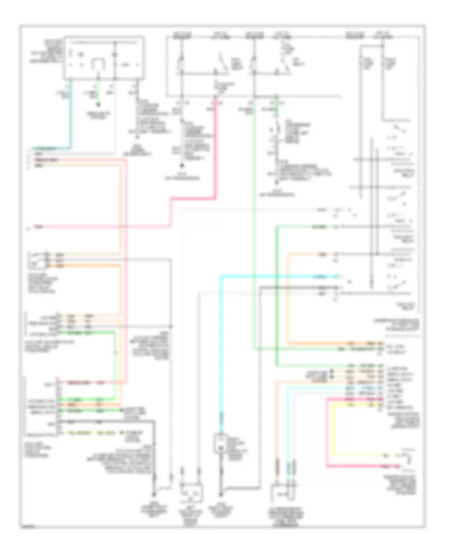
Automatic A/C Wiring Diagram (2 of 2) for Cadillac DTS 2006
List of elements for Automatic A/C Wiring Diagram (2 of 2) for Cadillac DTS 2006:
- (or 8)
- 14 cm (6 in) from branch to throttle body assembly)
- 5v ref 1
- A/c compressor clutch (lower left side of engine)
- A/c fuse 10a
- A/c ref
- A/c refrigerant pressure sensor (on a/c pressure hose, near compressor)
- A/c relay
- Auxiliary blower motor (if equipped) (bottom of hvac module)
- Auxiliary blower motor control module (if equipped)
- Auxiliary hvac control module (if equipped)
- Backlmp ctrl
- Batt
- Computer data lines system
- Cool/fan 1 relay
- Cool/fan 2 relay
- Cool/fan relay
- Ect sens sig
- Engine control module (ecm) (left side of engine compt)
- Engine coolant temperature (ect) sensor (on right rear of engine)
- Fan 1 fuse 30a
- Fan 2 fuse 30a
- Feed back sig
- G104 (right front of engine compt)
- G112 (on transmission)
- G115 (on transmission)
- G300 (under driver's seat)
- G304 (under front passenger's seat)
- Gnd
- Headlights system
- Hi spd fan
- Hot at all times
- Hot in on or start
- Hvac/ipc fuse 10a
- Interior lights system
- Left cooling fan (front of engine compt)
- Low ref
- Mtr spd ctrl
- Pnk
- Right cooling fan (front of engine compt)
- Rly ctrl
- Run/ crnk relay
- S105 (in engine harness, approximately
- S106 (in engine harness, approximately 7 cm (3 in) from branch to throttle body assembly)
- S228 (in hvac harness, between auxiliary blower motor control module & auxiliary blower motor)
- S383 (w/o auxiliary a/c) (in center console harness, between breakout to a/t shift lock control solenoid & breakout to auxiliary hvac control module)
- Serial data
- Serial data +
- Serial data -
- Sunload twilight sensor (on top center of dash, in defogger grill)
- Tan
- Underhood fuse block (at right side of engine compt)
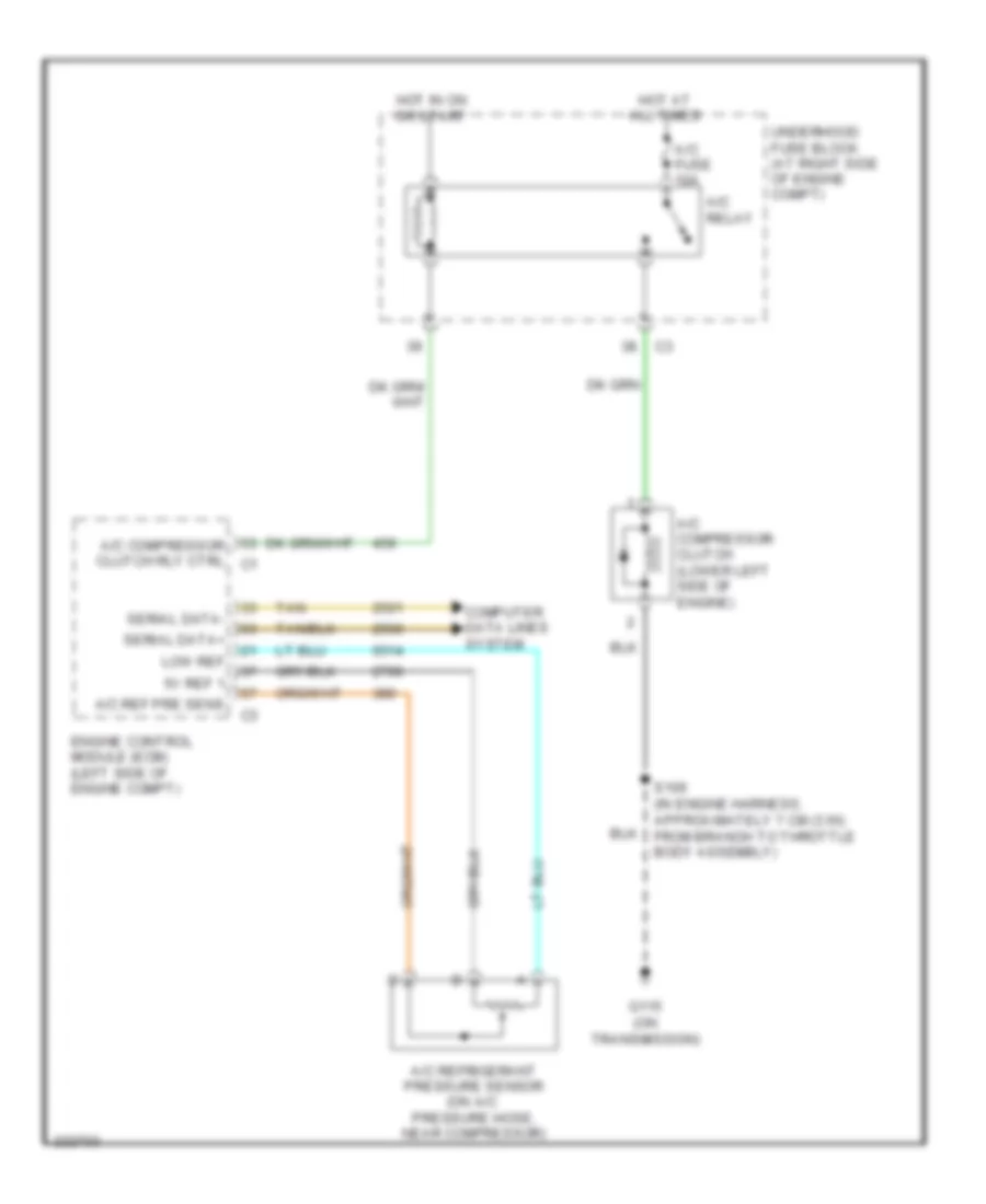
Compressor Wiring Diagram for Cadillac DTS 2006
List of elements for Compressor Wiring Diagram for Cadillac DTS 2006:
- 5v ref 1
- A/c compressor clutch (lower left side of engine)
- A/c compressor clutch rly ctrl c1
- A/c fuse 10a
- A/c ref pre sens
- A/c refrigerant pressure sensor (on a/c pressure hose, near compressor)
- A/c relay
- Computer data lines system
- Engine control module (ecm) (left side of engine compt)
- G115 (on transmission)
- Hot at all times
- Hot in on or start
- Low ref
- S106 (in engine harness, approximately 7 cm (3 in) from branch to throttle body assembly)
- Serial data+
- Serial data-
- Tan
- Underhood fuse block (at right side of engine compt)