AIR CONDITIONING
Heater Wiring Diagram for Jeep Liberty Renegade 2004

List of elements for Heater Wiring Diagram for Jeep Liberty Renegade 2004:
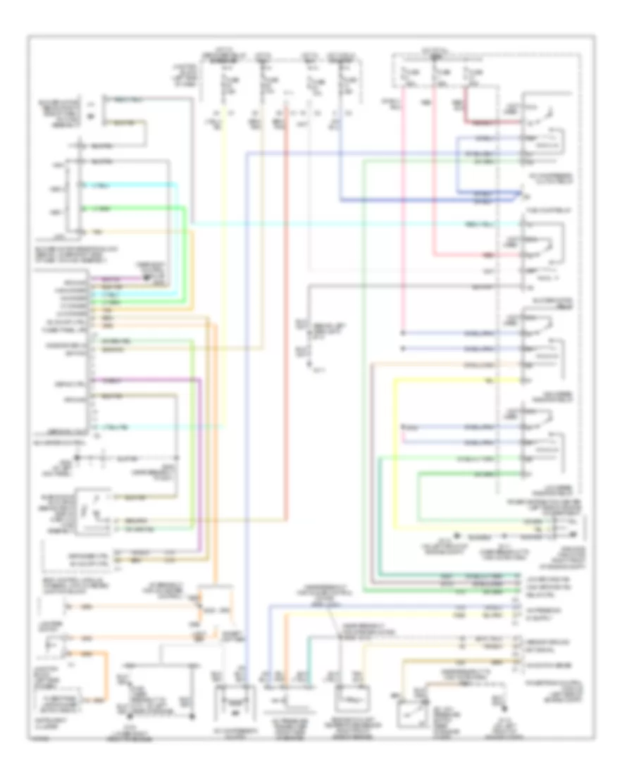
Manual A/C Wiring Diagram for Jeep Liberty Renegade 2004
List of elements for Manual A/C Wiring Diagram for Jeep Liberty Renegade 2004: