HEADLIGHTS
Adaptive Front Lighting Wiring Diagram for Cadillac XLR V 2009

List of elements for Adaptive Front Lighting Wiring Diagram for Cadillac XLR V 2009:
- Abs/mrrtd/ afs fuse 1 10a
- Bare
- Battery positive voltage
- Computer data lines system
- Drain wire
- E10
- G102
- Gmlan data bus +
- Gmlan data bus -
- Ground
- Headlamp act - left sig 1
- Headlamp act - left sig 2
- Headlamp act - left sig 3
- Headlamp act - left sig 4
- Headlamp act - right sig 1
- Headlamp act - right sig 2
- Headlamp act - right sig 3
- Headlamp act - right sig 4
- Headlamp module (right rear corner of engine compt)
- Hot at all times
- Hot w/ run/crank relay energized
- Ignition 1 voltage
- Left adaptive forward lighting (afl) motor (inside left front headlamp assembly)
- Pnk
- Right adaptive forward lighting (afl) motor (inside right front headlamp)
- Splice pack jx102 (in forward lamp harness, in engine compt, on upper right frame rail, grounded to g102)
- Tan
- Underhood fuse block (right rear of engine compt)
- W/s wash/ intercool fuse 17 15a
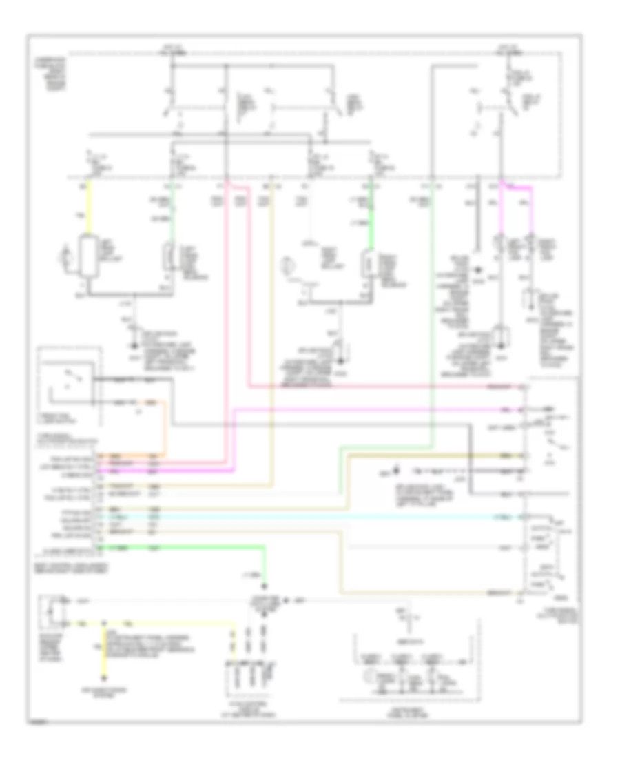
Headlamps Wiring Diagram for Cadillac XLR V 2009
List of elements for Headlamps Wiring Diagram for Cadillac XLR V 2009:
- (bcm) class 2
- (not used)
- Air conditioning system
- Auto
- Body control module (bcm) (behind right side of dash)
- C10
- Class 2 (bcm)
- Class 2 ser data
- Computer data lines system
- D10
- F11
- Fog lamps on
- Fog lmp rly ctrl
- Fog lmp sw sig
- Fog lp fuse 22 15a
- Fog lp relay
- Front fog lamp switch
- Ftp
- Ftp sw sig
- G101
- G102
- G201
- Hdlmps off
- Hdlmps on
- Head
- Head- lamps on ind
- Hi beam sig
- Hi bm rly ctrl
- High
- High beam ind
- High beam relay
- Hot at all times
- Hvac control module (at center of dash)
- Instrument panel cluster
- J119
- J120
- J242 (in instrument panel harness, approximately 11.5 cm from inflatable restraint sensing & diagnostic module)
- J275
- Left front fog lamp
- Left head- lamp ballast
- Left head- lamp high beam solenoid
- Low
- Low beam relay
- Low beam rly ctrl
- Low ref
- Lt hi bm fuse 24 10a
- Lt lo bm fuse 21 20a
- Nca
- Off
- Park
- Prk lmp on sig
- Right front fog lamp
- Right head- lamp ballast
- Right head- lamp high beam solenoid
- Rt hi bm fuse 23 10a
- Rt lo bm fuse 19 20a
- Sen sig
- Ser data
- Splice pack jx101 (in forward lamp harness, in engine compt, on upper left frame rail, grounded to g101)
- Splice pack jx102 (in forward lamp harness, in engine compt, on upper right frame rail, grounded to g102)
- Splice pack jx201 (in instrument panel harness, at base of left "a" pillar)
- Sunload sensor (upper center of dash)
- Turn signal/ multi-function switch
- Turn signal/ multifunction switch
- Underhood fuse block (right rear of engine compt)