AIR CONDITIONING
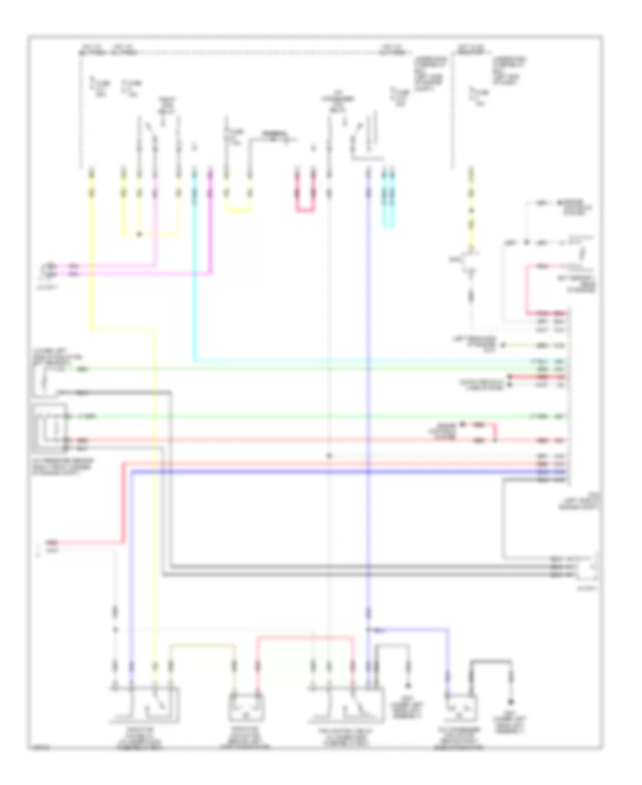
Automatic A/C Wiring Diagram, Except Hybrid (1 of 3) for Honda Civic HF 2014

List of elements for Automatic A/C Wiring Diagram, Except Hybrid (1 of 3) for Honda Civic HF 2014:
- (right side of hvac unit) mode control motor
- Air mix control motor (on left side of hvac assembly)
- Automatic lighting/ sunlight sensor (top center of dash)
- Blower motor (bottom of blower unit)
- Blower motor relay
- C204
- C208
- C413
- Computer data lines system
- Coupe
- Defogger system
- Evaporator temperature sensor (left side of hvac evaporator assembly)
- Fuse 2-8 40a
- G401 (left kick panel)
- G504 (right end of dash)
- Hot at all times
- Humidity sensor
- Humidity/in-car temperature sensor (left center of dash)
- Hvac control unit/ climate control unit
- In-car temperature sensor
- Interior lights system
- J/c c006
- Outside air temperature sensor (behind left side of front bumper)
- Pnk
- Power transistor (bottom of blower unit)
- Recirculation control motor (left side of blower unit)
- Red
- Sedan
- Under-hood fuse/relay box (left side of engine compt)
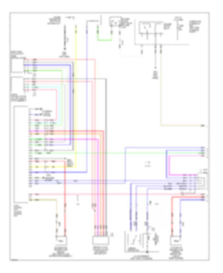
Automatic A/C Wiring Diagram, Except Hybrid (2 of 3) for Honda Civic HF 2014
List of elements for Automatic A/C Wiring Diagram, Except Hybrid (2 of 3) for Honda Civic HF 2014:
- 10v stabilizing circuit
- 5v control circuit
- 5v regulator
- A/c compressor (left front of engine)
- A10
- A11
- B-can h
- B-can l
- B-can transceiver
- C13
- C17
- C407
- Center junction box 1
- Center junction box 2
- Clutch compressor a/c
- Computer data lines system
- Coupe
- D14
- Dimming circuit
- Econ ind (led)
- Econ switch
- Fuse 15a
- Fuse 7.5a
- G501 (left end of dash)
- G502 (left side of dash)
- Gauge control module (tach)
- H10
- Hot in on
- Hot in on or start
- Indicator drive circuit
- Interior lights system
- Main circuit
- Micu
- On/off 5v
- Pnk
- Red
- Relay control module
- Sedan
- Thermal protector
- Under-dash fuse/relay box (under left end of dash)
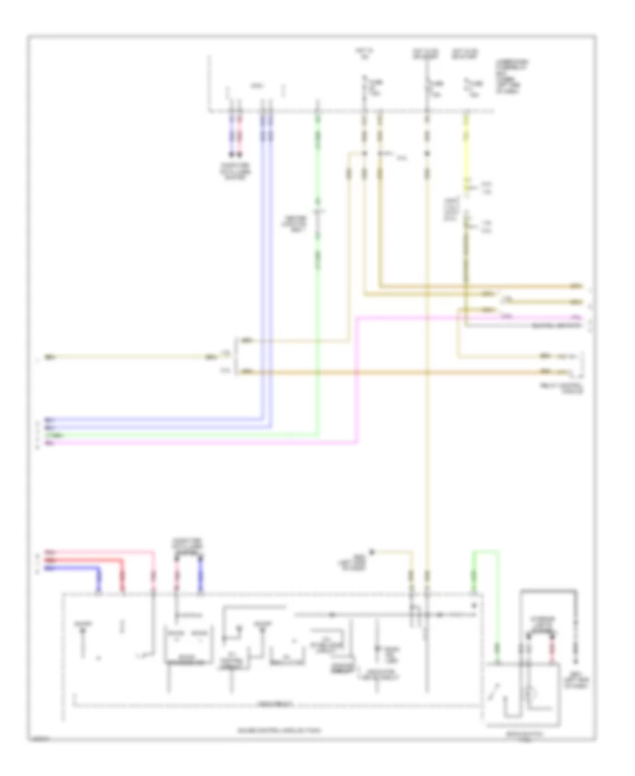
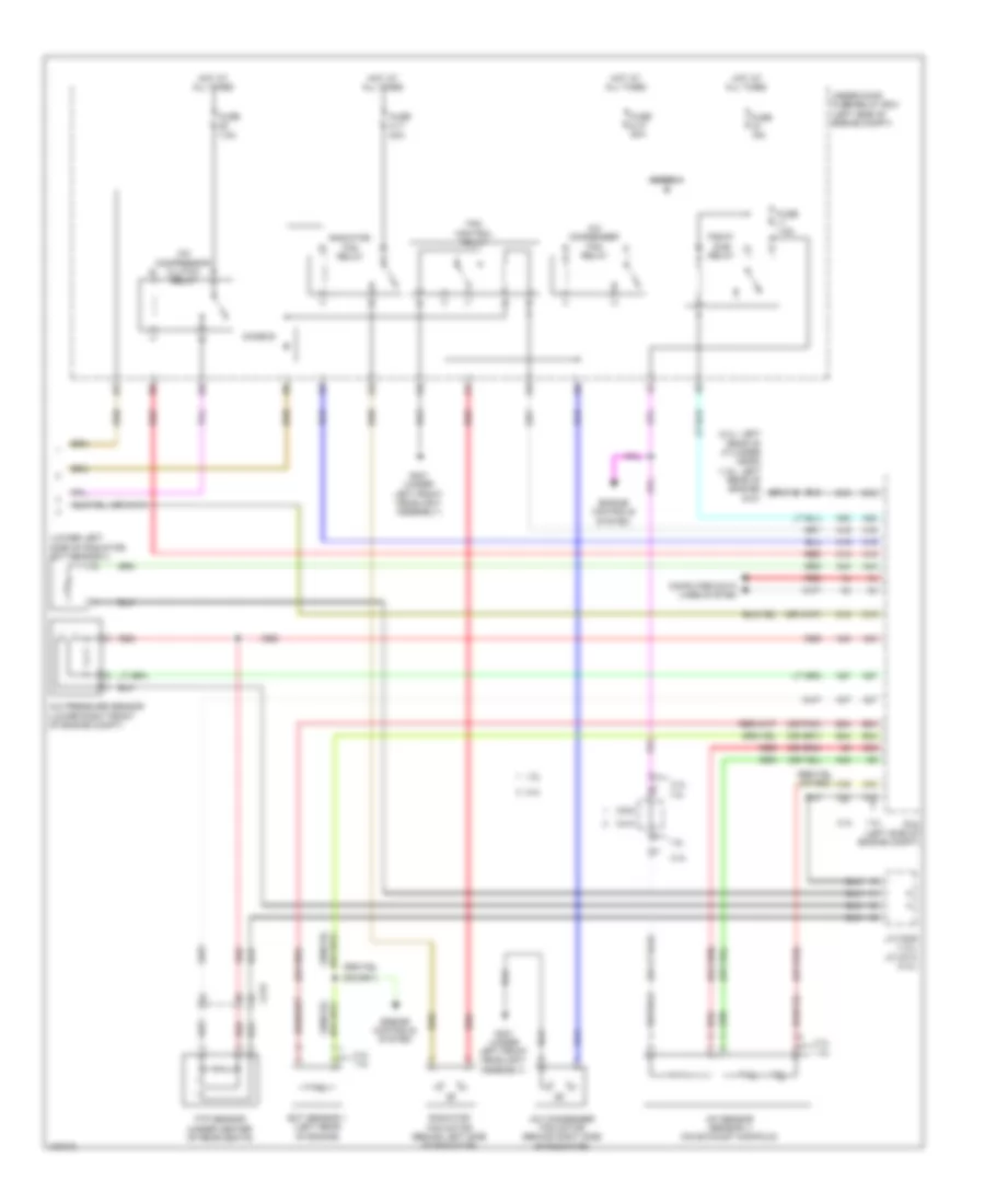
Automatic A/C Wiring Diagram, Except Hybrid (3 of 3) for Honda Civic HF 2014
List of elements for Automatic A/C Wiring Diagram, Except Hybrid (3 of 3) for Honda Civic HF 2014:
- (2.4l: left rear of cylinder head) (1.8l: left rear of engine) g101
- (lower left side of radiator) ect sensor 2
- A/c compressor clutch relay
- A/c condenser fan motor (behind right side of radiator)
- A/c condenser fan relay
- A/c pressure sensor (lower right front of engine compt)
- A/f sensor (sensor 1) (on exhaust manifold)
- A10
- A12
- A15
- A16
- A20
- A27
- A30
- A37
- A46
- B19
- B34
- B42
- B43
- B44
- C215
- C407
- Computer data lines system
- Diode a
- Diode b
- Ect sensor 1 (left rear of engine)
- Engine controls system
- Fan control relay
- Ftp sensor (under center of rear seats)
- Fuse 15a
- Fuse 2-10 20a
- Fuse 2-11 20a
- Fuse 7.5a
- G301 (under left front headlight assembly)
- Hot at all times
- J/c c005
- Pcm (left side of engine compt)
- Pgm-fi sub relay
- Radiator fan motor (behind left side of radiator)
- Radiator fan relay
- Red
- Under-hood fuse/relay box (left side of engine compt)
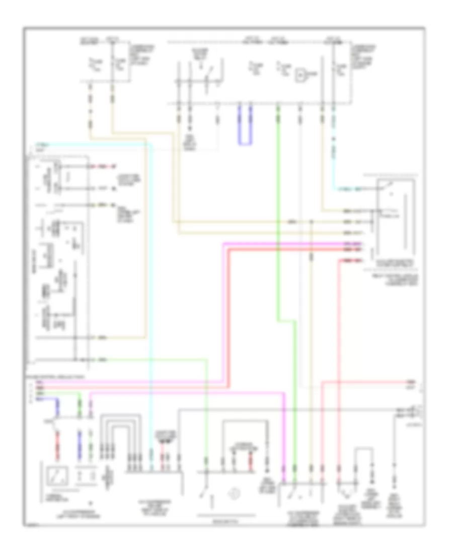
Automatic A/C Wiring Diagram, Hybrid (1 of 3) for Honda Civic HF 2014
List of elements for Automatic A/C Wiring Diagram, Hybrid (1 of 3) for Honda Civic HF 2014:
- (right side of hvac assembly) mode control motor
- Air mix control motor (left side of hvac assembly)
- Automatic lighting/ sunlight sensor (top center of windshield)
- Blower motor (bottom of blower unit)
- C204
- C205
- C208
- C209
- C222
- C306
- Climate control unit
- Computer data lines system
- D14
- Defogger system
- Evaporator temperature sensor (in evaporator)
- Fuse 7.5a
- G401 (left end of dash)
- G504 (upper right end of dash)
- Heater core temperature sensor (lower right side of hvac assembly)
- Hot in on or start
- Humidity/in-car temperature sensor (lower left center of dash)
- Interior lights system
- J/c c005
- Micu
- Outside air temperature sensor (behind left side of front bumper)
- Pnk
- Power transistor (near blower motor)
- Recirculation control motor (left side of blower unit)
- Red
- Under-dash fuse/relay box (left end of dash)
Automatic A/C Wiring Diagram, Hybrid (2 of 3) for Honda Civic HF 2014
List of elements for Automatic A/C Wiring Diagram, Hybrid (2 of 3) for Honda Civic HF 2014:
- (led) ind eco
- A/c compressor (left front of engine)
- A/c compressor clutch relay (in under-hood fuse/relay box)
- A/c compressor driver (right side of ipu module)
- A10
- A11
- Auxiliary electric water pump (right rear of engine compt)
- Auxiliary electric water pump relay
- B10
- Blower motor relay
- C17
- C302
- Circuit control
- Circuit stabilizing 10v
- Clutch compressor a/c
- Computer data lines system
- Dimming circuit
- Diode h
- Drive circuit indicator
- Econ switch
- F-can h
- F-can transceiver
- Fuse 2-8 40a
- Fuse 7.5a
- G301 (under left headlight assembly)
- G401 (left end of dash)
- G501 (upper left end of dash)
- G502 (upper left center of dash)
- G901 (right front corner of ipu module)
- Gauge control module (tach)
- Hot at all times
- Hot in on
- Hot in on or start
- Interior lights system
- J/c c014
- L f-can
- Main circuit
- Nca
- On/off
- Red
- Regulator 5v
- Relay control module (in under-hood fuse/relay box)
- Thermal protector
- Under-dash fuse/relay box (left end of dash)
- Under-hood fuse/relay box (left side of engine compt)
Automatic A/C Wiring Diagram, Hybrid (3 of 3) for Honda Civic HF 2014
List of elements for Automatic A/C Wiring Diagram, Hybrid (3 of 3) for Honda Civic HF 2014:
- (left rear side of engine) g101
- (lower left side of radiator) ect sensor 2
- A/c condenser fan motor (behind right side of radiator)
- A/c condenser fan relay
- A/c pressure sensor (right front corner of engine compt)
- A10
- A12
- A15
- A16
- A20
- A27
- A30
- A44
- B34
- B44
- C10
- C13
- C15
- C302
- Computer data lines system
- Diode g
- Ect sensor 1 (rear of engine)
- Engine controls system
- Fan control relay (in under-hood fuse/relay box)
- Fuse 15a
- Fuse 2-10 20a
- Fuse 2-11 20a
- Fuse 7.5a
- G301 (under left headlight assembly)
- Hot at all times
- Hot in on or start
- J/c c011
- Pcm (left side of engine compt)
- Pgm-fi sub relay
- Pnk
- Radiator fan motor (behind left side of radiator)
- Radiator fan relay (in under-hood fuse/relay box)
- Red
- Under-dash fuse/relay box (left end of dash)
- Under-hood fuse/relay box (left side of engine compt)
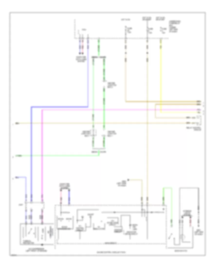
Manual A/C Wiring Diagram (1 of 3) for Honda Civic HF 2014
List of elements for Manual A/C Wiring Diagram (1 of 3) for Honda Civic HF 2014:
- (or pnk)
- (right side of hvac unit) mode control motor
- 1.8l
- 1.8l 2.4l
- 2.4l
- 2.4l 1.8l
- A/c compressor (left front of engine)
- Air mix control motor (on left side of hvac assembly)
- Blower motor (bottom of blower unit)
- Blower motor relay
- C204
- C208
- C404
- C409
- C410
- C413
- Clutch compressor a/c
- Defogger system
- Evaporator temperature sensor (left side of hvac evaporator assembly)
- Fuse 2-8 40a
- G401 (left kick panel)
- G504 (right end of dash)
- Hot at all times
- Hvac control unit/ climate control unit
- Interior lights system
- Outside air temperature sensor (behind left side of front bumper)
- Pnk
- Power transistor (bottom of blower unit)
- Recirculation control motor (left side of blower unit)
- Red
- Thermal protector
- Under-hood fuse/relay box (left side of engine compt)
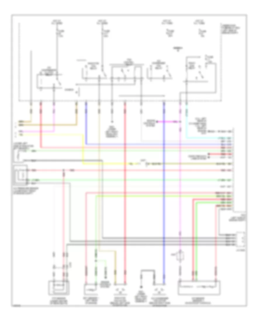
Manual A/C Wiring Diagram (2 of 3) for Honda Civic HF 2014
List of elements for Manual A/C Wiring Diagram (2 of 3) for Honda Civic HF 2014:
- 1.8l
- 10v stabilizing circuit
- 2.4l
- 5v control circuit
- 5v regulator
- A10
- A11
- B-can h
- B-can l
- B-can transceiver
- C13
- C17
- C404 (1.8l) c410 (2.4l)
- Center junction box 1
- Computer data lines system
- D14
- D17
- Dimming circuit
- Econ ind (led)
- Econ switch (1.8l)
- Fuse 15a
- Fuse 7.5a
- G501 (left end of dash)
- G502 (left side of dash)
- Gauge control module (tach)
- Hot in on
- Hot in on or start
- Indicator drive circuit
- Interior lights system
- Main circuit
- Micu
- On/off 5v
- Pnk
- Red
- Relay control module
- Under-dash fuse/relay box (under left end of dash)
- W12
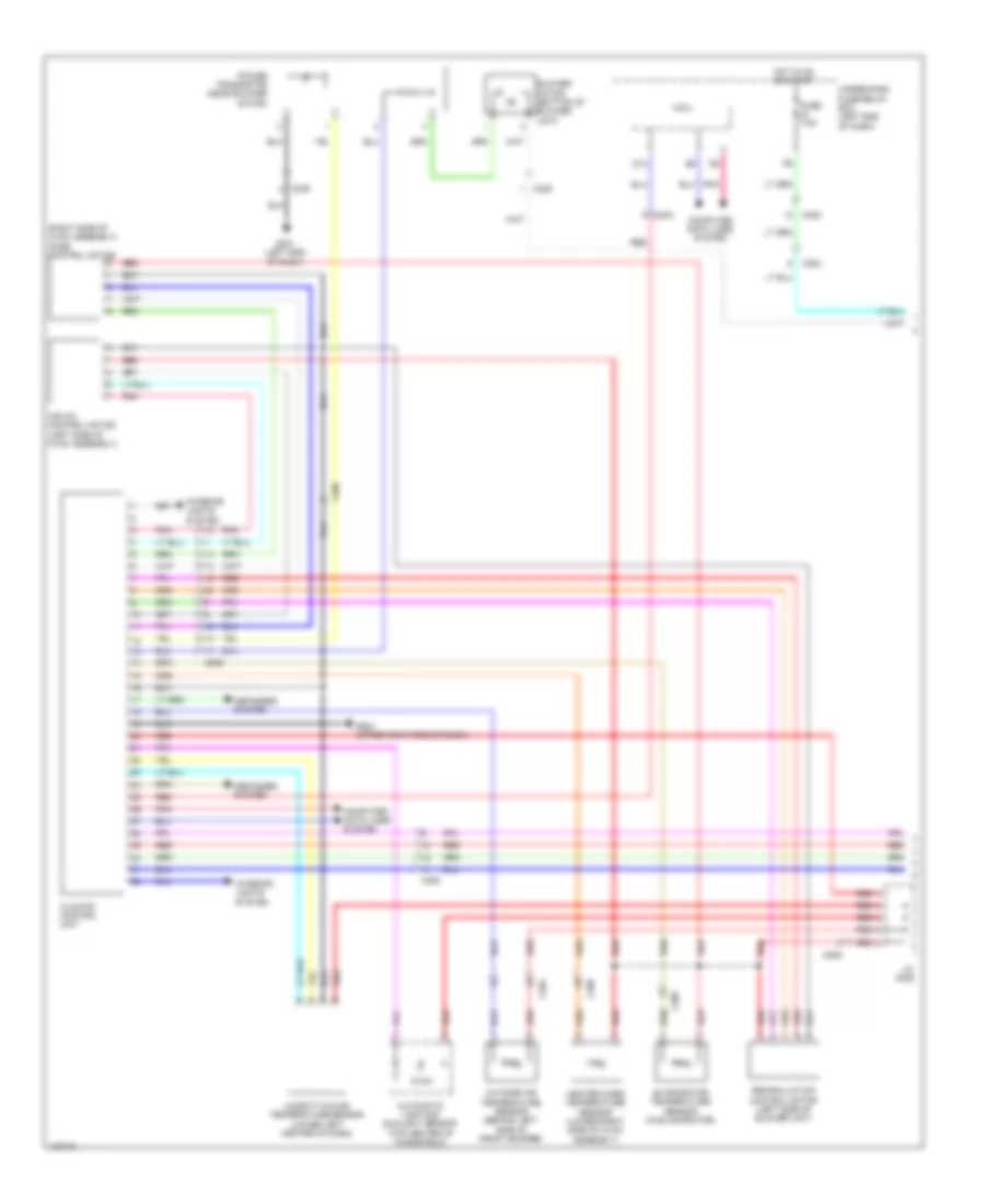
Manual A/C Wiring Diagram (3 of 3) for Honda Civic HF 2014
List of elements for Manual A/C Wiring Diagram (3 of 3) for Honda Civic HF 2014:
- (2.4l: left rear of cylinder head) (1.8l: left rear of engine) g101
- (lower left side of radiator) ect sensor 2
- (or pnk)
- (or red)
- 1.8l
- 2.4l
- 2.4l 1.8l
- A/c compressor clutch relay
- A/c condenser fan motor (behind right side of radiator)
- A/c condenser fan relay
- A/c pressure sensor (lower right front of engine compt)
- A/f sensor (sensor 1) (on exhaust manifold)
- A10
- A12
- A15
- A16
- A20
- A27
- A30
- A37
- A44
- B10
- B34
- B44
- C10
- C215
- C39
- C40
- C404
- C410
- Computer data lines system
- Diode a
- Diode b
- Ect sensor 1 (left rear of engine)
- Engine controls system
- Fan control relay
- Ftp sensor (under center of rear seats)
- Fuse 15a
- Fuse 2-10 20a
- Fuse 2-11 20a
- Fuse 7.5a
- G301 (under left front headlight assembly)
- Hot at all times
- J/c c009 (1.8l) j/c c012 (2.4l)
- Pcm (left side of engine compt)
- Pgm-fi sub relay
- Radiator fan motor (behind left side of radiator)
- Radiator fan relay
- Red
- Under-hood fuse/relay box (left side of engine compt)