AIR CONDITIONING
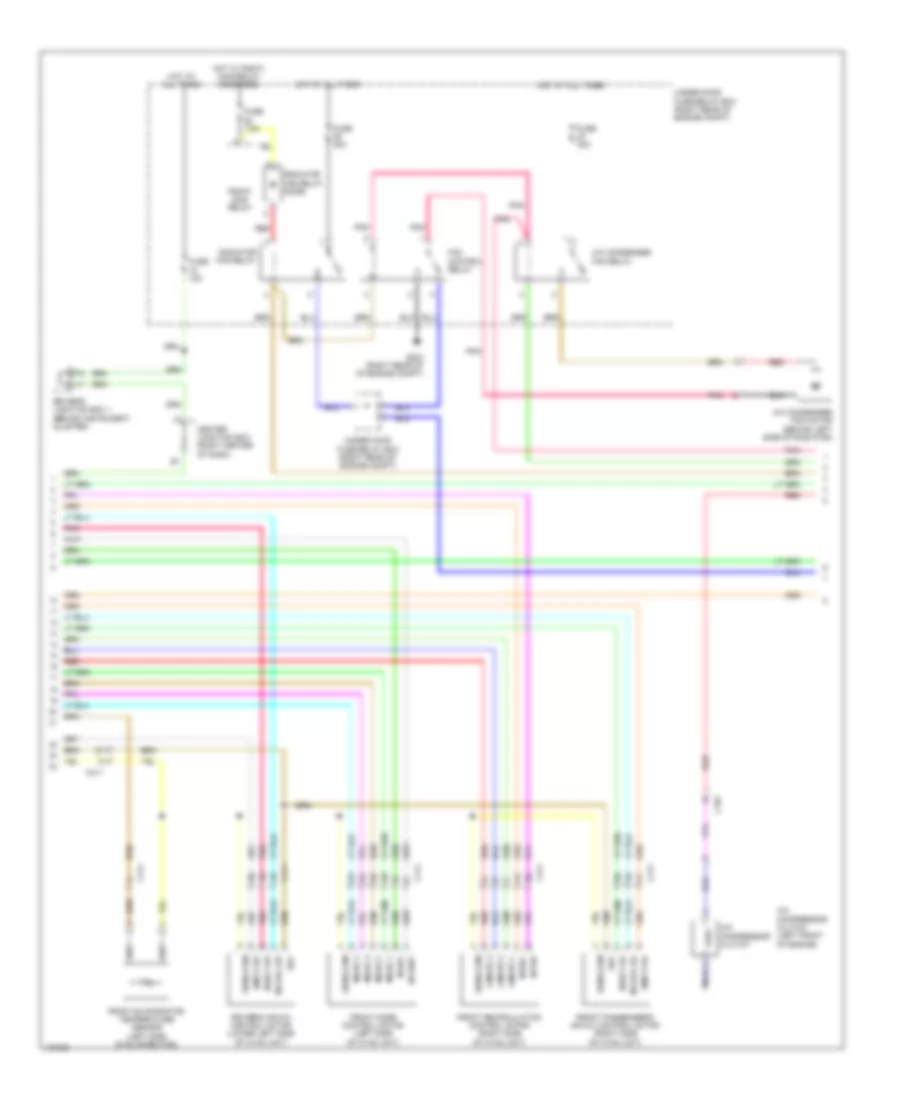
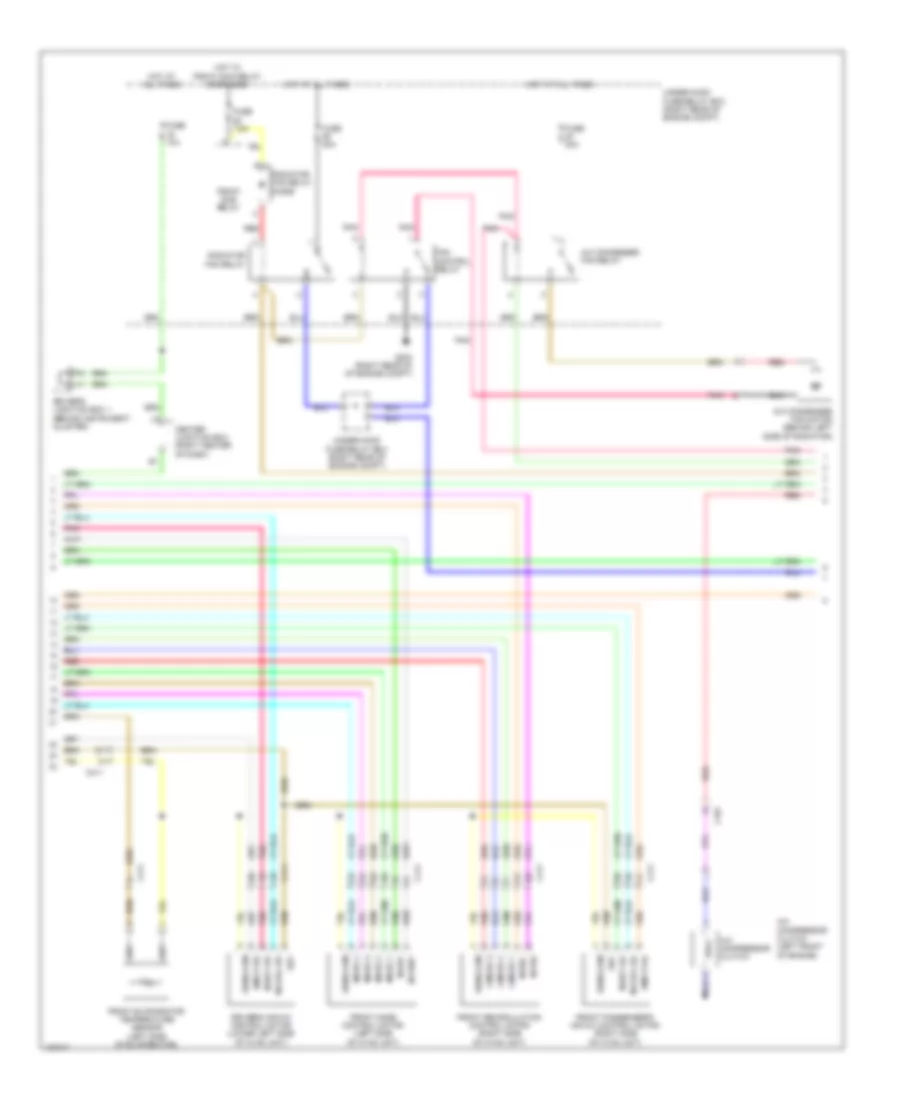
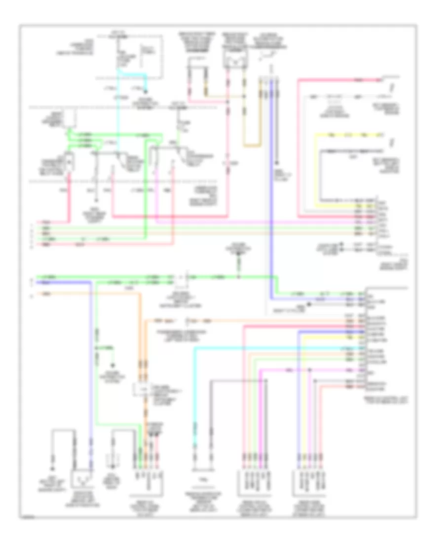
Automatic A/C Wiring Diagram, with Memory (1 of 3) for Honda Odyssey LX 2014

List of elements for Automatic A/C Wiring Diagram, with Memory (1 of 3) for Honda Odyssey LX 2014:
- (behind instrument cluster) driver's junction box 2
- (if equipped) cool box control switch
- A/c pressure sensor (right rear of engine compt)
- A10
- A11
- A12
- A13
- A14
- A15
- A16
- A17
- A18
- A19
- A20
- A21
- A22
- A23
- A24
- A25
- A26
- A27
- A28
- Amd-p-as
- Amd-p-dr
- Automatic lighting sensor/sunlight sensor (top center of dash)
- B-can h
- B-can hi
- B-can l
- B-can lo
- B10
- B11
- B12
- B13
- B14
- B15
- B16
- Batt
- Blw-g
- Blw-v
- Bus-data
- C/b bulb
- C/b open
- C/b sht
- C/b sw
- C202
- C205
- C208
- C410
- C411
- C413
- Climate control unit
- Computer data lines system
- Cool box control motor (if equipped) (left side of hvac blower housing)
- Driver's junction box 2 (behind instrument cluster)
- Driver's micu
- Driver's under-dash fuse/relay box (left end of dash)
- F17
- Fr blower fuse 40a
- Front blower motor (under right side of dash)
- Front blower motor relay
- Front blower power transistor (near front blower motor)
- Fuse 7.5a
- G204 (right end of dash)
- G302 (left end of dash)
- G403 (left center of dash)
- Gnd
- H10
- Hot at all times
- Hot in on
- Hum (hum-data)
- Humidity sensor
- Humidity/in-car temperature sensor (lower left center of dash)
- Ig2
- Ill+
- Ill-
- In-car temperature sensor
- Interior lights system
- K10
- L-mode 1
- L-mode 2
- L-mode 3
- M-cool-as
- M-cool-dr
- M-def
- M-frs
- M-hot-as
- M-hot-dr
- M-rec
- M-vent
- Main under-hood fuse box (above transaxle)
- Mode 1
- Mode 2
- Mode 3
- Mode 4
- Multi- fuse 3
- Outside air temperature sensor (behind left side of front bumper)
- Pnk
- Red
- Relay block
- S5v
- Sens-com
- Sunlight sensor
- Tam
- Teva
- Tr (hum-clk)
- Tsun
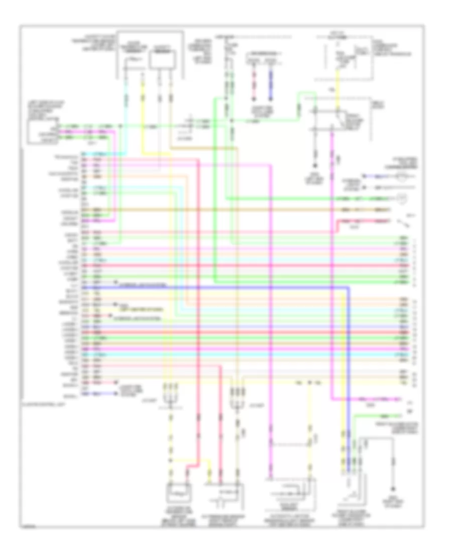
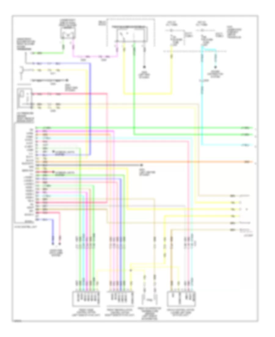
Automatic A/C Wiring Diagram, with Memory (2 of 3) for Honda Odyssey LX 2014
List of elements for Automatic A/C Wiring Diagram, with Memory (2 of 3) for Honda Odyssey LX 2014:
- A/c compressor clutch
- A/c compressor clutch (left front of engine)
- A/c condenser fan motor (behind left side of radiator)
- A/c condenser fan relay
- Amd-p-as
- Amd-p-dr
- C101
- C411
- Center junction box (right center of dash)
- Driver's air mix control motor (lower left side of hvac unit)
- Driver's junction box 1 (behind instrument cluster)
- Fan control relay
- Front evaporator temperature sensor (left side of evaporator)
- Front mode control motor (left side of hvac unit)
- Front passenger's air mix control motor (right side of hvac unit)
- Front recirculation control motor (right side of hvac unit)
- Fuse 10a
- Fuse 30a
- Fuse 7.5a
- G203 (right rear of of engine compt)
- Hot at all times
- Hot w/ pgm-fi main relay energized
- L-mode 1
- L-mode 2
- L-mode 3
- M-cool-as
- M-cool-dr
- M-def
- M-frs
- M-hot-as
- M-hot-dr
- M-rec
- M-vent
- Mode 1
- Mode 2
- Mode 3
- Mode 4
- Pgm-fi sub relay
- Pnk
- Radiator fan relay
- Radiator fan relay diode
- Red
- S5v
- Sens-com
- Under-hood fuse/relay box (right rear of engine compt)
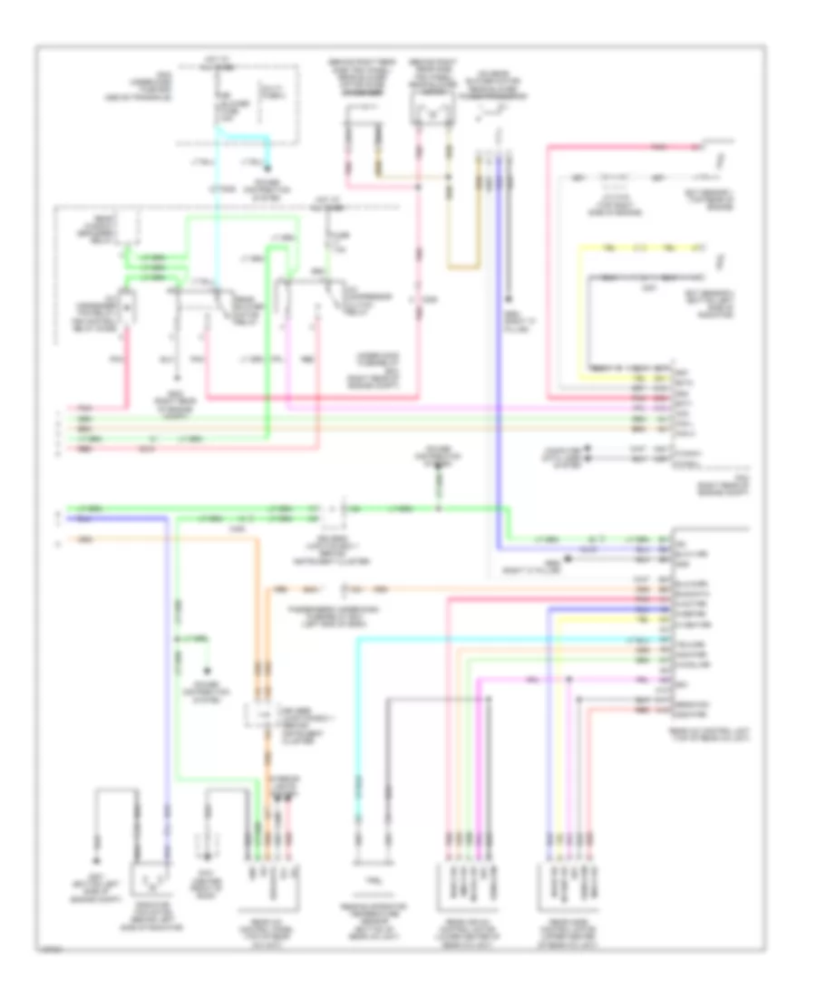
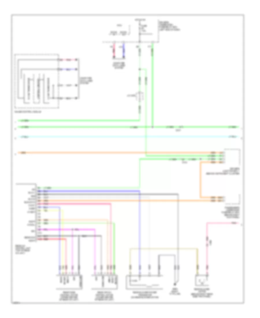
Automatic A/C Wiring Diagram, with Memory (3 of 3) for Honda Odyssey LX 2014
List of elements for Automatic A/C Wiring Diagram, with Memory (3 of 3) for Honda Odyssey LX 2014:
- (behind right rear side trim panel) rear blower motor
- (behind right rear side trim panel) rear blower motor noise condenser
- (on rear blower motor) rear blower power transistor
- A/c compressor clutch relay
- A/c condenser fan relay/ fan control relay diode
- A10
- A11
- A12
- A13
- A21
- A37
- A48
- A49
- Acc
- Amd-p-rr
- Blw-g-rr
- Blw-v-rr
- Bus-data
- C16
- C201
- C206
- C208
- C210
- C32
- C405
- C415
- Computer data lines system
- D31
- Driver's junction box 1 (behind instrument cluster)
- E42
- Ect sensor 1 (top rear of engine)
- Ect sensor 2 (bottom left side of radiator)
- Ect1
- Ect2
- F-can-h
- F-can-l
- Fan h
- Fan l
- Fuse 7.5a
- G201 (bottom left side of engine compt)
- G203 (right rear of engine compt)
- G652 (right "c" pillar)
- G701 (center front of roof)
- Gnd
- Hot at all times
- Ig2
- Ill+
- Ill-
- Interior lights system
- J/c c104 (top right side of engine)
- M-cool-rr
- M-def-rr
- M-hot-rr
- M-vent-rr
- Main under-hood fuse box (above transaxle)
- Mdd-p-rr
- Multi- fuse 2
- Passenger's under-dash fuse/relay box (left end of dash)
- Pcm (right rear of engine compt)
- Pnk
- Power distribution system
- Radiator fan motor (behind left side of radiator)
- Rear a/c control panel (top of rear a/c unit)
- Rear a/c control unit (top of rear a/c unit)
- Rear air mix control motor (lower center of rear a/c unit)
- Rear blower motor relay
- Rear evaporator temperature sensor (bottom of rear a/c unit)
- Rear mode control motor (upper center of rear a/c unit)
- Rear window defogger relay
- Red
- Rr blower fuse 30a
- S5v
- Sens-com
- Sg2
- Sg7
- Teva-rr
- Under-hood fuse/relay box (right rear of engine compt)
Automatic A/C Wiring Diagram, without Memory (1 of 3) for Honda Odyssey LX 2014
List of elements for Automatic A/C Wiring Diagram, without Memory (1 of 3) for Honda Odyssey LX 2014:
- (if equipped) cool box control switch
- (left side of hvac blower housing) (if equipped) cool box control motor
- A/c pressure sensor (right rear of engine compt)
- A10
- A11
- A12
- A13
- A14
- A15
- A16
- A17
- A18
- A19
- A20
- A21
- A22
- A23
- A24
- A25
- A26
- A27
- A28
- Amd-p-as
- Amd-p-dr
- Automatic lighting sensor/sunlight sensor (top center of dash)
- B-can h
- B-can hi
- B-can l
- B-can lo
- B10
- B11
- B12
- B13
- B14
- B15
- B16
- Batt
- Blw-g
- Blw-v
- Bus-data
- C/b bulb
- C/b open
- C/b sht
- C/b sw
- C202
- C205
- C208
- C410
- C411
- C413
- Climate control unit
- Computer data lines system
- Driver's micu
- Driver's under-dash fuse/relay box (left end of dash)
- F17
- Fr blower fuse 40a
- Front blower motor (under right side of dash)
- Front blower motor relay
- Front blower power transistor (under right side of dash)
- Fuse 7.5a
- G204 (right end of dash)
- G302 (left end of dash)
- G403 (left center of dash)
- Gnd
- H10
- Hot at all times
- Hot in on
- Hum (hum-data)
- Humidity sensor
- Humidity/in-car temperature sensor (lower left center of dash)
- Ig2
- Ill+
- Ill-
- In-car temperature sensor
- Interior lights system
- J/c c407
- J/c c408
- L-mode 1
- L-mode 2
- L-mode 3
- M-cool-as
- M-cool-dr
- M-def
- M-frs
- M-hot-as
- M-hot-dr
- M-rec
- M-vent
- Main under-hood fuse box (above transaxle)
- Mode 1
- Mode 2
- Mode 3
- Mode 4
- Multi- fuse 3
- Outside air temperature sensor (behind left side of front bumper)
- Pnk
- Red
- Relay block
- S5v
- Sens-com
- Sunlight sensor
- Tam
- Teva
- Tr (hum-clk)
- Tsun
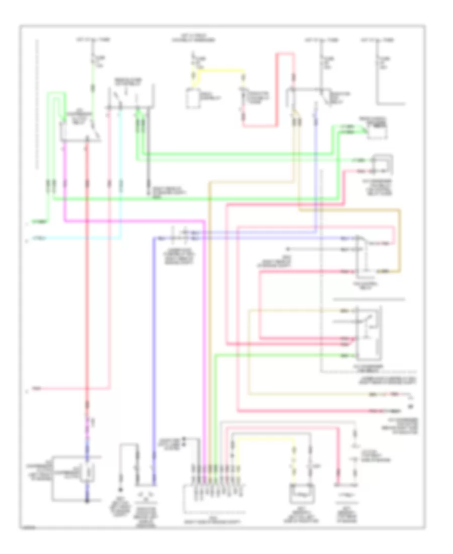
Automatic A/C Wiring Diagram, without Memory (2 of 3) for Honda Odyssey LX 2014
List of elements for Automatic A/C Wiring Diagram, without Memory (2 of 3) for Honda Odyssey LX 2014:
- A/c compressor clutch
- A/c compressor clutch (left front of engine)
- A/c condenser fan motor (behind left side of radiator)
- A/c condenser fan relay
- Amd-p-as
- Amd-p-dr
- C101
- C411
- Center junction box (right center of dash)
- Driver's air mix control motor (lower left side of hvac unit)
- Driver's junction box 1 (behind instrument cluster)
- Fan control relay
- Front evaporator temperature sensor (left side of evaporator)
- Front mode control motor (left side of hvac unit)
- Front passenger's air mix control motor (right side of hvac unit)
- Front recirculation control motor (right side of hvac unit)
- Fuse 10a
- Fuse 30a
- Fuse 7.5a
- G203 (right rear of of engine compt)
- Hot at all times
- Hot w/ pgm-fi main relay energized
- L-mode 1
- L-mode 2
- L-mode 3
- M-cool-as
- M-cool-dr
- M-def
- M-frs
- M-hot-as
- M-hot-dr
- M-rec
- M-vent
- Mode 1
- Mode 2
- Mode 3
- Mode 4
- Pgm-fi sub relay
- Pnk
- Radiator fan relay
- Radiator fan relay diode
- Red
- S5v
- Sens-com
- Under-hood fuse/relay box (right rear of engine compt)
Automatic A/C Wiring Diagram, without Memory (3 of 3) for Honda Odyssey LX 2014
List of elements for Automatic A/C Wiring Diagram, without Memory (3 of 3) for Honda Odyssey LX 2014:
- (behind right rear side trim panel) rear blower motor
- (behind right rear side trim panel) rear blower motor noise condenser
- (on rear blower motor) rear blower power transistor
- A/c compressor clutch relay
- A/c condenser fan relay/ fan control relay diode
- A10
- A11
- A12
- A13
- A21
- A37
- A48
- A49
- Acc
- Amd-p-rr
- Blw-g-rr
- Blw-v-rr
- Bus-data
- C16
- C201
- C206
- C208
- C210
- C32
- C405
- C415
- Computer data lines system
- D31
- Driver's junction box 1 (behind instrument cluster)
- E42
- Ect sensor 1 (top rear of engine)
- Ect sensor 2 (bottom left side of radiator)
- Ect1
- Ect2
- F-can-h
- F-can-l
- Fan h
- Fan l
- Fuse 7.5a
- G201 (bottom left front of engine compt)
- G203 (right rear of engine compt)
- G652 (right "c" pillar)
- G701 (center front of roof)
- Gnd
- Hot at all times
- Ig2
- Ill+
- Ill-
- Interior lights system
- J/c c104 (top right side of engine)
- M-cool-rr
- M-def-rr
- M-hot-rr
- M-vent-rr
- Main under-hood fuse box (above transaxle)
- Mod-p-rr
- Multi- fuse 2
- Passenger's under-dash fuse/relay box (left end of dash)
- Pcm (right side of engine compt)
- Pnk
- Power distribution system
- Radiator fan motor (behind left side of radiator)
- Rear a/c control panel (top of rear a/c unit)
- Rear a/c control unit (top of rear a/c unit)
- Rear air mix control motor (lower center of rear a/c unit)
- Rear blower motor relay
- Rear evaporator temperature sensor (bottom of rear a/c unit)
- Rear mode control motor (upper center of rear a/c unit)
- Rear window defogger relay
- Red
- Rr blower fuse 30a
- S5v
- Sens-com
- Sg2
- Sg7
- Teva-rr
- Under-hood fuse/relay box (right rear of engine compt)
Manual A/C Wiring Diagram (1 of 3) for Honda Odyssey LX 2014
List of elements for Manual A/C Wiring Diagram (1 of 3) for Honda Odyssey LX 2014:
- (near front blower motor) front blower power transistor
- (under right side of dash) front blower motor
- A/c pressure sensor (right rear of engine compt)
- Air mix control motor (lower left side of hvac unit)
- Amd-p
- B-can h
- B-can l
- Blw-g
- Blw-v
- Bus data
- C202
- C205
- C208
- C411
- Computer data lines system
- Fr blower fuse 40a
- Front blower motor relay
- Front evaporator temperature sensor (left side of evaporator)
- Front mode control motor (left side of hvac unit)
- Front recirculation control motor (right side of hvac unit)
- G204 (right end of dash)
- G302 (left end of dash)
- G403 (left center of dash)
- Gnd
- Hot at all times
- Hvac control unit
- Ig2
- Ill+
- Ill-
- Interior lights system
- J/c c407
- L-mode 1
- L-mode 2
- L-mode 3
- M-cool
- M-def
- M-frs
- M-hot
- M-rec
- M-vent
- Main under-hood fuse box (above transaxle)
- Mode 1
- Mode 2
- Mode 3
- Mode 4
- Multi- fuse 2
- Multi- fuse 3
- Pnk
- Power distribution system
- Red
- Relay block
- Rr blower fuse 30a
- S5v
- Sens com
- Sens-com
- Teva
Manual A/C Wiring Diagram (2 of 3) for Honda Odyssey LX 2014
List of elements for Manual A/C Wiring Diagram (2 of 3) for Honda Odyssey LX 2014:
- A10
- A11
- A12
- Amd-p
- B can transceiver
- B-can hi
- B-can lo
- Blw-g
- Blw-v
- Bus data
- C206
- C210
- C415
- Computer data lines system
- Control circuits
- D31
- Driver's junction box 1 (behind instrument cluster)
- Driver's under-dash fuse/relay box (left end of dash)
- E42
- F can transceiver
- F17
- Fuse 7.5a
- G652 (right "c" pillar)
- Gauge control module
- Gnd
- H10
- Hot in on
- Ig2
- J/c c408
- M-cool
- M-def
- M-hot
- M-vent
- Mdd-p
- Micu
- Passenger's under-dash fuse/relay box (behind right kick panel)
- Pnk
- Rear a/c control unit (top of rear a/c unit)
- Rear air mix control motor (lower center of rear a/c unit)
- Rear blower motor (behind right rear side trim panel)
- Rear blower power transistor (on rear blower motor)
- Rear mode control motor (upper center of rear a/c unit)
- Red
- S5v
- Sens-com
Manual A/C Wiring Diagram (3 of 3) for Honda Odyssey LX 2014
List of elements for Manual A/C Wiring Diagram (3 of 3) for Honda Odyssey LX 2014:
- (right rear of of engine compt) g203
- A/c compressor clutch
- A/c compressor clutch (left front of engine)
- A/c compressor clutch relay
- A/c condenser fan motor (behind right side of radiator)
- A/c condenser fan relay
- A/c condenser fan relay/ fan control relay diode
- A13
- A21
- A37
- A48
- A49
- A5 fan h
- Acc
- C101
- C16
- C32
- Computer data lines system
- Ect sensor 1 (top rear of engine)
- Ect sensor 2 (bottom left side of radiator)
- Ect1
- Ect2
- F-can h
- F-can l
- Fan control relay
- Fan l
- Fuse 30a
- Fuse 7.5a
- G201 (bottom left front of engine compt)
- G203 (right rear of of engine compt)
- Hot at all times
- Hot w/ pgm-fi main relay energized
- J/c c104 (top right side of engine)
- Pcm (right side of engine compt)
- Pgm-fi sub-relay
- Pnk
- Radiator fan motor (behind left side of radiator)
- Radiator fan relay
- Radiator fan relay diode
- Rear blower motor relay
- Rear window defogger relay
- Red
- Sg2
- Sg7
- Under-hood fuse/relay box (right rear of engine compt)