ANTI-LOCK BRAKES
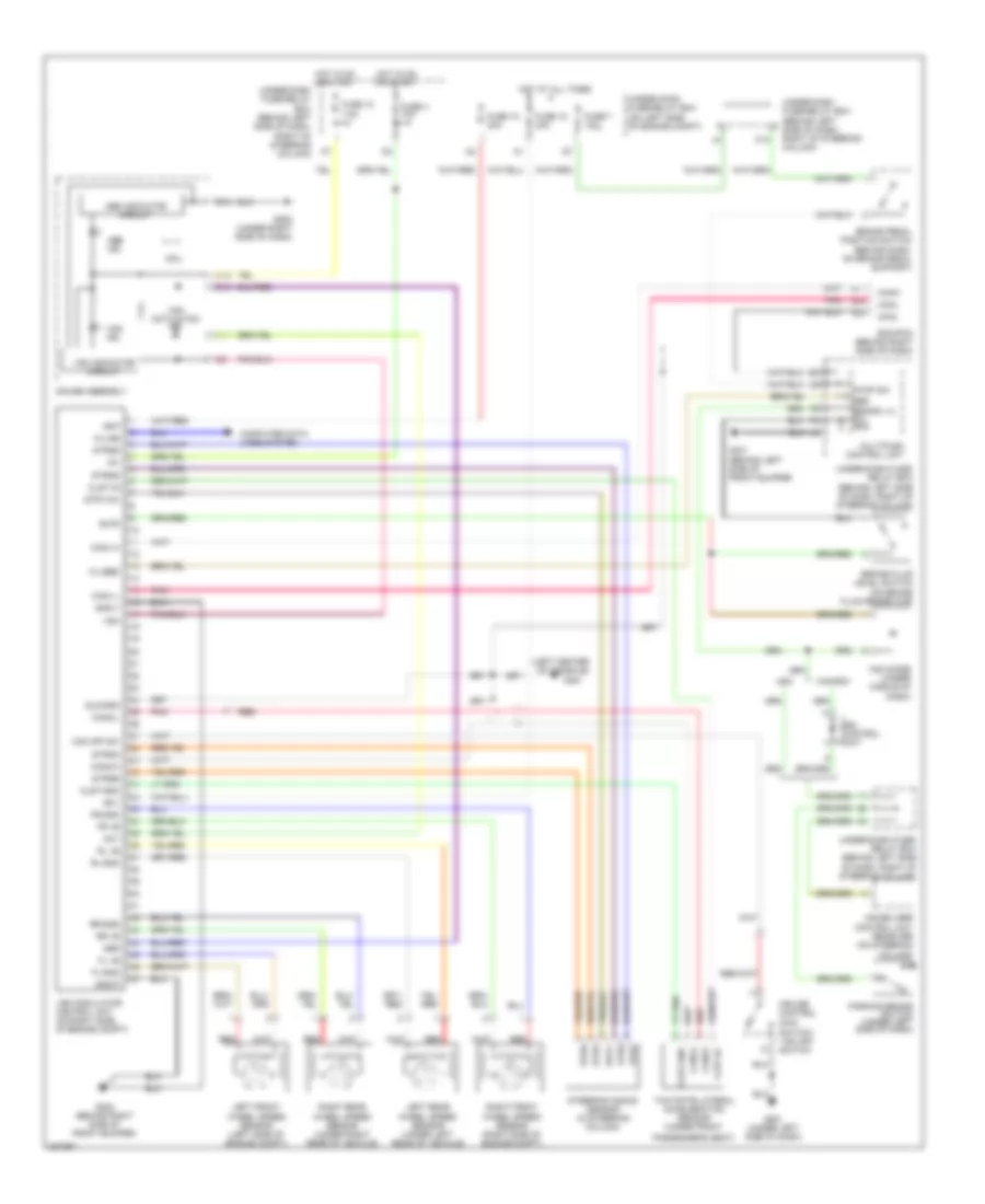
Anti-lock Brakes Wiring Diagram for Honda CR-V LX 2006
List of elements for Anti-lock Brakes Wiring Diagram for Honda CR-V LX 2006:
- (left center of console)
- +b-p
- +b-v
- Abs
- Abs ind
- Abs indicator circuit
- Act
- Blfs
- Brake fluid level switch (on brake fluid reservoir)
- Brake pedal position switch (behind dash, on brake pedal support)
- Can1-h
- Can1-l
- Can2-h
- Can2-l
- Can22
- Can24
- Canada
- Canh
- Canl
- Clst-gnd
- Clst-ig
- Computer data lines system
- Cpu
- Cruise control main
- Drl control unit
- E11
- E22
- E24
- Ecm/pcm (behind right side of dash)
- Fl +b
- Fl-gnd
- Fr +b
- Fr-gnd
- Fuse 10 30a
- Fuse 10 7.5a
- Fuse 18 30a
- Fuse 4 10a
- Fuse 7 15a
- G202 (behind right side of front bumper)
- G301 (behind left side of front bumper)
- G451
- G501 (under left side of dash)
- G502 (under right side of dash)
- Gauge assembly
- Gnd-p
- Gnd-v
- Hot at all times
- Hot in on or start
- Ig1
- Immobilizer control unit receiver (on steering column)
- K-line
- Left front wheel speed sensor (left side of engine compt)
- Left rear wheel speed sensor (under left rear of vehicle)
- Multiplex control unit
- O12
- Parking brake switch (under left side of dash)
- Passenger's seat)
- Pnk
- Red
- Right front wheel speed sensor (right side of engine compt)
- Right rear wheel speed sensor (under right rear of vehicle)
- Rl +b
- Rl-gnd
- Rr +b
- Rr-gnd
- Sld-gnd
- Steering angle sensor (in steering column)
- Stop sw
- Str-vcc
- Stra
- Strb
- Strg
- Strga
- Strgb
- Strgg
- Strgz
- Strz
- Svcc
- Switch/ vsa off switch
- Under-dash fuse/ relay box (behind left side of dash, right of steering column)
- Under-dash fuse/relay box (behind left side of dash, right of steering column)
- Under-hood fuse/relay box (on left side of engine compt)
- Usa
- Vsa
- Vsa activation ind
- Vsa diode (under middle of dash)
- Vsa ind
- Vsa indicator circuit
- Vsa modulator control unit (on right side of engine compt)
- Vsa off sw
- Wl-ebd
- Y1 ebd brake lvl sw gnd
- Yaw rate-lateral acceleration sensor (under front
 English