ANTI-LOCK BRAKES
Anti-lock Brakes Wiring Diagram (1 of 2) for Honda CR-V LX 2014

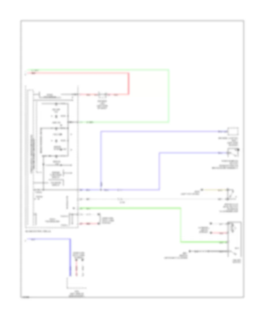
List of elements for Anti-lock Brakes Wiring Diagram (1 of 2) for Honda CR-V LX 2014:
- (behind instrument cluster)
- A11
- Brake pedal position switch (top of brake pedal assembly)
- C120
- C126
- C16
- Computer data lines system
- D11
- D14
- D17
- Driver's micu
- Eps control unit (left side of dash)
- Fuse 1-3 40a
- Fuse 1-4 20a
- Fuse 10a
- Fuse 7.5a
- G201 (right rear of engine compt)
- G501
- Hot at all times
- Hot in on or start
- Left front wheel speed sensor (on left front wheel hub assembly)
- Left rear wheel speed sensor (on left rear wheel hub assembly)
- P15
- Pnk
- Q16
- Red
- Right front wheel speed sensor (on right front wheel hub assembly)
- Right rear wheel speed sensor (on right rear wheel hub assembly)
- Steering angle sensor (in steering column)
- Under-dash fuse/ relay box (under left end of dash)
- Under-hood fuse/relay box (on left side of engine compt)
- Vsa modulator control unit (right rear of engine compt)
- W/ rear entertainment system
- W/o navigation &
Anti-lock Brakes Wiring Diagram (2 of 2) for Honda CR-V LX 2014
List of elements for Anti-lock Brakes Wiring Diagram (2 of 2) for Honda CR-V LX 2014:
- A13
- Abs ind
- Brake fluid level switch (on brake fluid reservoir)
- Brake ind
- Brake system ind
- C108
- Computer data lines system
- Dc/dc converter
- Driver's j/b 2 (left side of dash)
- Driver's junction box 1 (left side of dash)
- F-can h
- F-can l
- F-can transceiver
- Fail-safe circuit
- Forced turning-on circuit
- G402 (left kick panel)
- G501 (behind instrument cluster)
- Gauge control module
- Indicator drive circuit
- Interior lights system
- Parking brake switch (base of parking brake lever assembly)
- Pcm (left side of engine compt)
- Red
- Vsa ind
- Vsa off ind
- Vsa off switch