ANTI-LOCK BRAKES
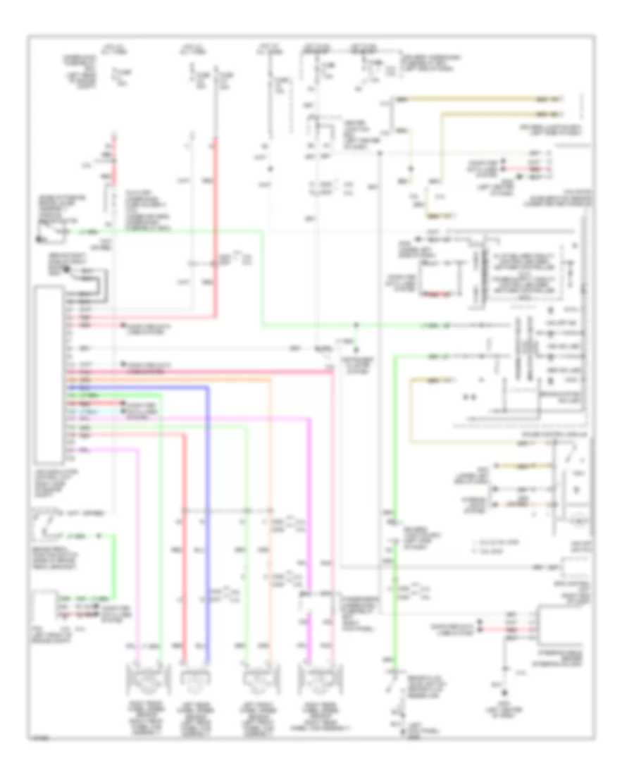
Anti-lock Brakes Wiring Diagram for Honda Crosstour EX-L 2014
List of elements for Anti-lock Brakes Wiring Diagram for Honda Crosstour EX-L 2014:
- (3.5l)
- (base of parking brake lever assembly) parking brake switch
- (behind right side of front bumper) g202
- (left kick panel) g302
- (or red)
- 2.4l
- 2.4l & 3.5l 4wd
- 2.4l 3.5l
- 3.5l
- 3.5l 2.4l
- 3.5l 2wd
- A10
- A25
- A42
- Abs ind (led)
- Auxiliary under-dash fuse holder a (3.5l) (under driver's under-dash fuse/relay box)
- Brake fluid level switch (brake fluid reservoir)
- Brake pedal position switch (base of brake pedal bracket)
- Brake system ind (led)
- C202
- C204 c201
- C205
- C306
- C401
- C404
- C408
- Center junction box (left center of dash)
- Computer data lines system
- D27
- Driver's junction box (left side of dash)
- Driver's under-dash fuse/relay box (left end of dash)
- E10
- Eps control unit (right end of dash)
- F-can h
- F-can l
- F-can transceiver
- Fuse 10a
- Fuse 2-2 40a
- Fuse 2-3 30a
- Fuse 20a
- Fuse 7.5a
- G401 (upper left end of dash)
- G402 (under left side of dash)
- G403 (left center of dash)
- Gauge control module
- H22
- H23
- Hot at all times
- Hot in on or start
- Indicator drive circuit (2.4l)
- Instrument cluster system
- Interior lights system
- Left front wheel speed sensor (left front wheel hub assembly)
- Left rear wheel speed sensor (left rear wheel hub assembly)
- Passenger's under-dash fuse/relay box (right kick panel)
- Pcm (left front of engine compt)
- Pnk
- Red
- Right front wheel speed sensor (right front wheel hub assembly)
- Right rear wheel speed sensor (right rear wheel hub assembly)
- Steering angle sensor (steering column)
- Under-hood fuse/relay box (left rear of engine compt)
- Vsa ind (led)
- Vsa modulator control unit (right side of engine compt)
- Vsa off ind
- Vsa off switch
- Warning drive circuit
- Yaw rate- acceleration sensor (under center console)
 English