ANTI-LOCK BRAKES
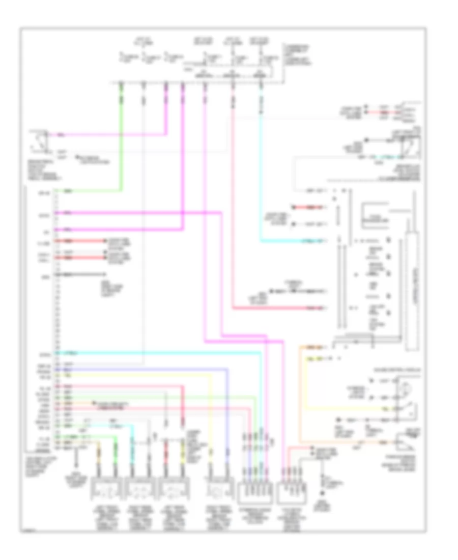
Anti-lock Brakes Wiring Diagram for Honda Insight LX 2014
List of elements for Anti-lock Brakes Wiring Diagram for Honda Insight LX 2014:
- (thermal joint) s6
- +b backup
- A18
- A23
- A32
- A42
- Abs ind
- B28
- Bksw
- Brake fluid level switch (on master cylinder reservoir)
- Brake ind
- Brake pedal position switch (top of brake pedal assembly)
- Brake system ind
- C10
- C201
- C302
- C304
- C407
- Can h
- Can l
- Computer data lines system
- Control circuits
- Exterior lights system
- F-can transceiver
- Fl +b
- Fl-gnd
- Fr +b
- Fr-gnd
- Fsr +b
- Fuse 1 15a
- Fuse 11 7.5a
- Fuse 22 7.5a
- Fuse 24 10a
- Fuse 37 30a
- Fuse 58 30a
- G203 (right side of engine compt)
- G403 (left side of dash)
- G501 (left end of dash)
- G502 (center of dash)
- Gauge control module
- Gnd
- Hot at all times
- Hot in on or start
- Ig1
- Ig1 abs/vsa
- Ig1 meter
- Interior lights system
- K line
- Left front wheel speed sensor (left front wheel hub assembly)
- Left rear wheel speed sensor (left rear wheel hub assembly)
- Micu
- Mr +b
- Mr-gnd
- Parking brake switch (base of parking brake lever)
- Pcm (left front of engine compt)
- Pnk
- Q16
- Red
- Right front wheel speed sensor (right front wheel hub assembly)
- Right rear wheel speed sensor (right rear wheel hub assembly)
- Rl +b
- Rl-gnd
- Rr +b
- Rr-gnd
- S6 (thermal joint)
- Sgnd
- Steering angle sensor (on steering column)
- Str-a
- Str-b
- Str-z
- Svcc
- Under- dash fuse/ relay box (under left side of dash)
- Under-dash fuse/relay box (under left side of dash)
- Vsa modulator- control unit (right side of engine compt)
- Vsa off ind
- Vsa off switch
- Vsa system ind
- Wen
- Yaw rate- lateral acceleration sensor (center of dash)
 English