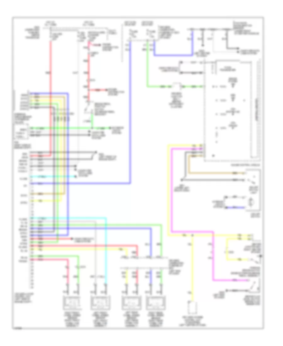
ANTI-LOCK BRAKES
Anti-lock Brakes Wiring Diagram for Honda Odyssey LX 2014
List of elements for Anti-lock Brakes Wiring Diagram for Honda Odyssey LX 2014:
- A48
- A49
- Abs ind
- Bksw
- Brake fluid level switch (brake fluid reservoir)
- Brake pedal position switch (on brake pedal bracket)
- Brake system ind
- C210
- C212
- C302
- Center junction box (right center of dash)
- Computer data lines system
- Control circuits
- Driver's junction box 1 (behind instrument cluster)
- Driver's under-dash fuse/relay box (left end of dash)
- E35
- E36
- E38
- E39
- Exterior lights system
- F-can h
- F-can l
- F-can transceiver
- F15
- F16
- F18
- F19
- F31
- Fl +b
- Fl-gnd
- Fr +b
- Fr-gnd
- Fsr +b
- Fuse 7.5a
- Fuse 9 20a
- G13
- G301 (left front of engine compt)
- G302 (left end of dash)
- G401 (upper left end of dash)
- G403 (left center of dash)
- Gauge control module
- Gnd
- Hot at all times
- Hot in on or start
- Ig 1
- Ig1
- Interior lights system
- K-line
- Keyless access control unit (if equipped) (left center of dash)
- Left front wheel speed sensor (left front wheel hub assembly)
- Left rear wheel speed sensor (left rear wheel hub assembly)
- Main under-hood fuse box (above transaxle)
- Mr+b
- Mr-gnd
- Multi- fuse 2
- Parking brake switch (base of parking brake pedal assembly)
- Pcm (right side of engine compt)
- Pnk
- Power distribution system
- Red
- Right front wheel speed sensor (right front wheel hub assembly)
- Right rear wheel speed sensor (right rear wheel hub assembly)
- Rl +b
- Rl-gnd
- Rr +b
- Rr-gnd
- Sgnd
- Steering angle sensor (in steering column)
- Stop & horn hazard fuse 30a
- Str-a
- Str-b
- Str-z
- Svcc
- Vsa fsr fuse 30a
- Vsa modulator control unit (left side of engine compt)
- Vsa mtr fuse 40a
- Vsa off ind
- Vsa off switch
- Vsa off switch light
- Vsa system ind
- Wen
- Yaw rate acceleration sensor (under front of center console)
 English