ANTI-LOCK BRAKES
Anti-lock Brakes Wiring Diagram (1 of 2) for Honda Pilot EX 2006

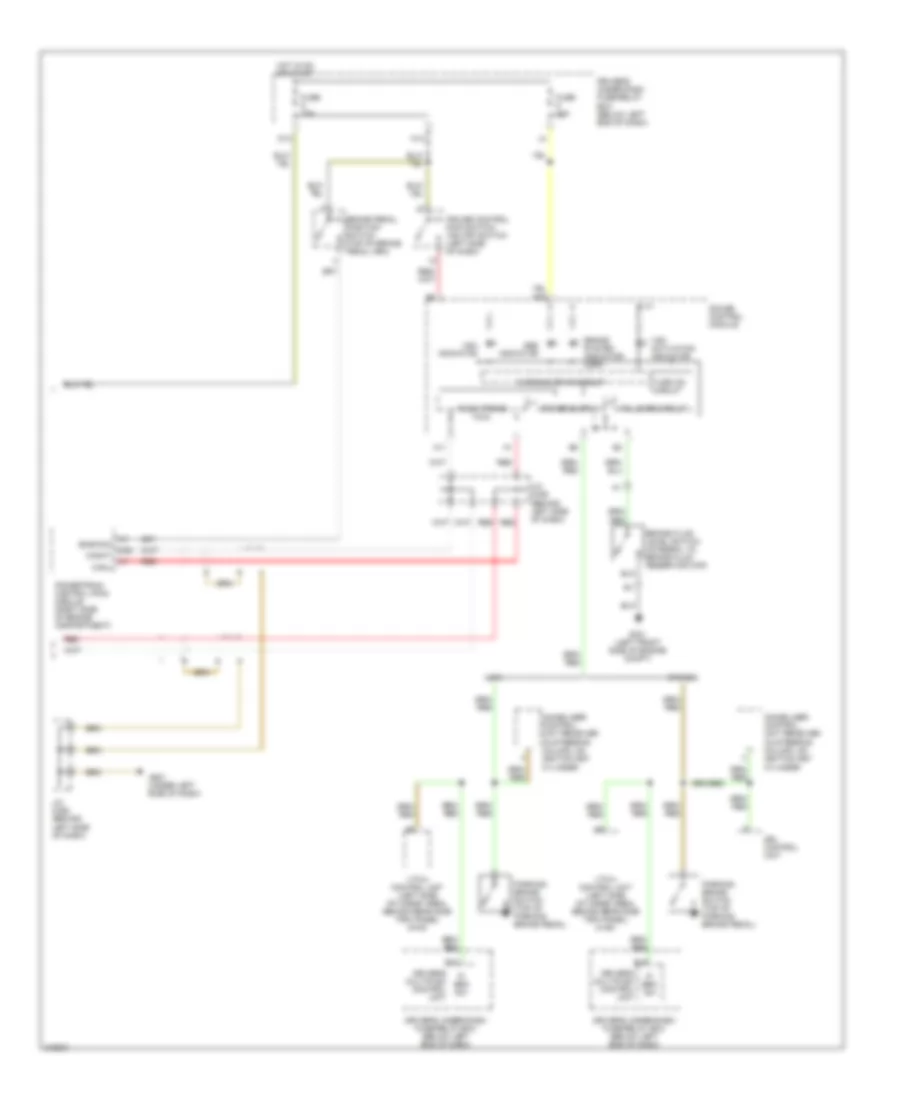
List of elements for Anti-lock Brakes Wiring Diagram (1 of 2) for Honda Pilot EX 2006:
- (4wd)
- (left side of engine compete)
- (not used)
- (under center console) yaw rate-lateral acceleration sensor
- +b-fsr
- +b-mr
- Auxiliary fuse box (left side of engine compt)
- Can-h
- Can-l
- Computer data lines system
- Driver's under-dash fuse/relay box (below left end of dash)
- F13
- F14
- Flp
- Fls (+)
- Fls (-)
- Frp
- Frs (+)
- Frs (-)
- Fuse 30a
- Fuse 40a
- G302 (below driver's under- dash fuse/relay box)
- Glat
- Glong
- Gnd
- Hot at all times
- Ig1
- J17
- K-line
- Left front wheel speed sensor (left side of engine compt)
- Left rear wheel speed sensor (under rear of vehicle)
- M10
- Mr-gnd
- Rap
- Red
- Right front wheel speed sensor (right side of engine compt)
- Right rear wheel speed sensor (under rear of vehicle)
- Rls (+)
- Rls (-)
- Rrp
- Rrs (+)
- Rrs (-)
- S-gnd
- Sgnd
- Steering angle sensor (in steering column)
- Str-a
- Str-b
- Str-d
- Stra
- Strb
- Strz
- Svcc
- Transmissions system
- Vas modulator control unit
- Yaw
Anti-lock Brakes Wiring Diagram (2 of 2) for Honda Pilot EX 2006
List of elements for Anti-lock Brakes Wiring Diagram (2 of 2) for Honda Pilot EX 2006:
- A11
- A36
- Abs indicator
- B15
- Bkswnc
- Brake fluid level switch (integral to brake fluid reservoir cap)
- Brake pedal position switch (top of brake pedal arm)
- Brake system indicator (usa)
- Canada
- Canhy
- Canl
- Cruise control main switch/ vsa off switch (left side of dash)
- D13
- Driver's multiplex control unit
- Driver's under-dash fuse/relay box (below left end of dash)
- Drl control unit
- F-can trans
- Fail safe circuit
- Fuse 10a
- Fuse 15a
- G301 (left front side of engine compt)
- G501 (under left side of dash)
- Gauge control module
- Hot in on or start
- Immobilizer control unit receiver (in steering column, on ignition key cylinder
- J/c c306 (behind left side of dash)
- M14
- P/ brk sw
- Parking brake switch (top of parking brake pedal)
- Powertrain control (pcm) module (right side of engine compartment)
- Red
- Turn on circuit
- Usa
- Vsa activation indicator
- Vsa indicator
- Vtm-4 control unit (left side of cargo area, behind rear side trim panel) (4wd)
- Warning drive circuit