ANTI-LOCK BRAKES
Anti-lock Brakes Wiring Diagram (1 of 2) for Honda Pilot Touring 2011

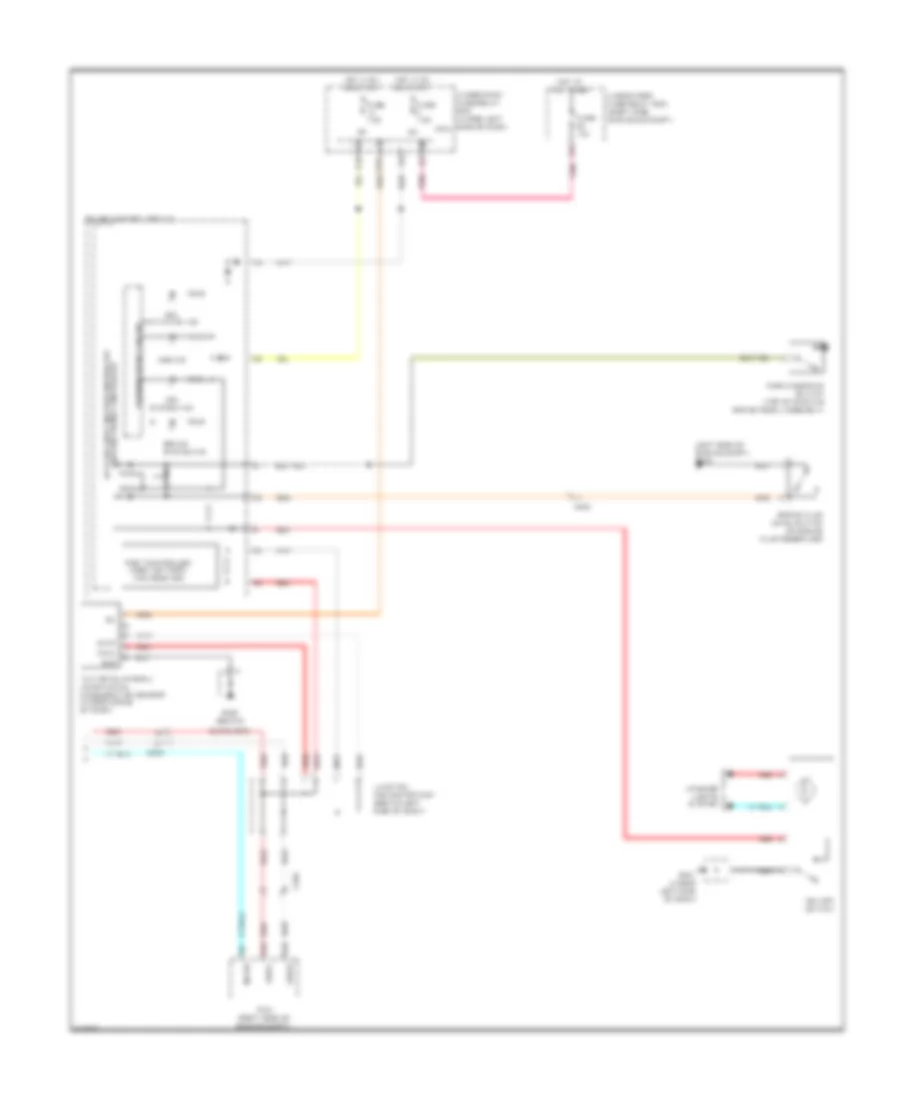
List of elements for Anti-lock Brakes Wiring Diagram (1 of 2) for Honda Pilot Touring 2011:
- +b stop & horn
- Auxiliary
- Brake pedal position switch (top of brake pedal assembly)
- C201
- C203
- C206
- C551
- Can-h
- Can-l
- Computer data
- Computer data lines
- F16
- F25
- F30
- F31
- Fl+b
- Fl-gnd
- Fr+b
- Fr-gnd
- Fsr+b
- Fuse 20a
- Fuse 4 40a
- Fuse 6 30a
- Fuse 7.5a
- G16
- G302 (under left front of engine compt)
- Gnd
- Hot at all times
- Hot in on or start
- Ig1
- K-line
- Left front wheel speed sensor (under left front of engine compt)
- Left rear wheel speed sensor (under left rear of vehicle)
- Lines system
- Micu
- Mr+b
- Mr-gnd
- Pnk
- Red
- Right front wheel speed sensor (under right front of engine compt)
- Right rear wheel speed sensor (under right rear of vehicle)
- Rl+b
- Rl-gnd
- Rr+b
- Rr-gnd
- Sgnd
- Steering angle sensor (in steering column)
- Str-a
- Str-b
- Str-d
- Svcc
- System
- Under-dash fuse/ relay box (under left side of dash)
- Under-hood fuse/relay box (left side of engine compt)
- Vsa modulator control unit (left side of engine compt)
- Wen
Anti-lock Brakes Wiring Diagram (2 of 2) for Honda Pilot Touring 2011
List of elements for Anti-lock Brakes Wiring Diagram (2 of 2) for Honda Pilot Touring 2011:
- (behind
- (left side of engine compt) g303
- 5v stabilizer circuit/controller area network controller
- A48
- A49
- Abs ind
- Bksw
- Brake fluid level switch (on brake fluid reservoir)
- Brake system ind
- C203
- C305
- Can-h
- Can-l
- Canh
- Canl
- Fast controller area network transceiver
- Fuse 10a
- Fuse 7.5a
- G401 (under left side of dash)
- G403
- Gauge control module
- Glove box)
- Gnd
- Hot at all times
- Hot in on or start
- Ig1
- Interior lights system
- Junction connector c421 (behind left side of dash)
- Micu
- P10
- Parking brake switch (top of parking brake pedal assembly)
- Pcm (right side of engine compt)
- Pnk
- R18
- Red
- Under-dash fuse/relay box (under left side of dash)
- Under-hood fuse/relay box (right side of engine compt)
- Vsa activation ind
- Vsa off switch
- Vsa system ind
- Warning drive circuit
- Yaw rate-lateral/ longitudinal acceleration sensor (under middle of dash)