ANTI-LOCK BRAKES
Anti-lock Brakes Wiring Diagram (1 of 2) for Honda Ridgeline RT 2008

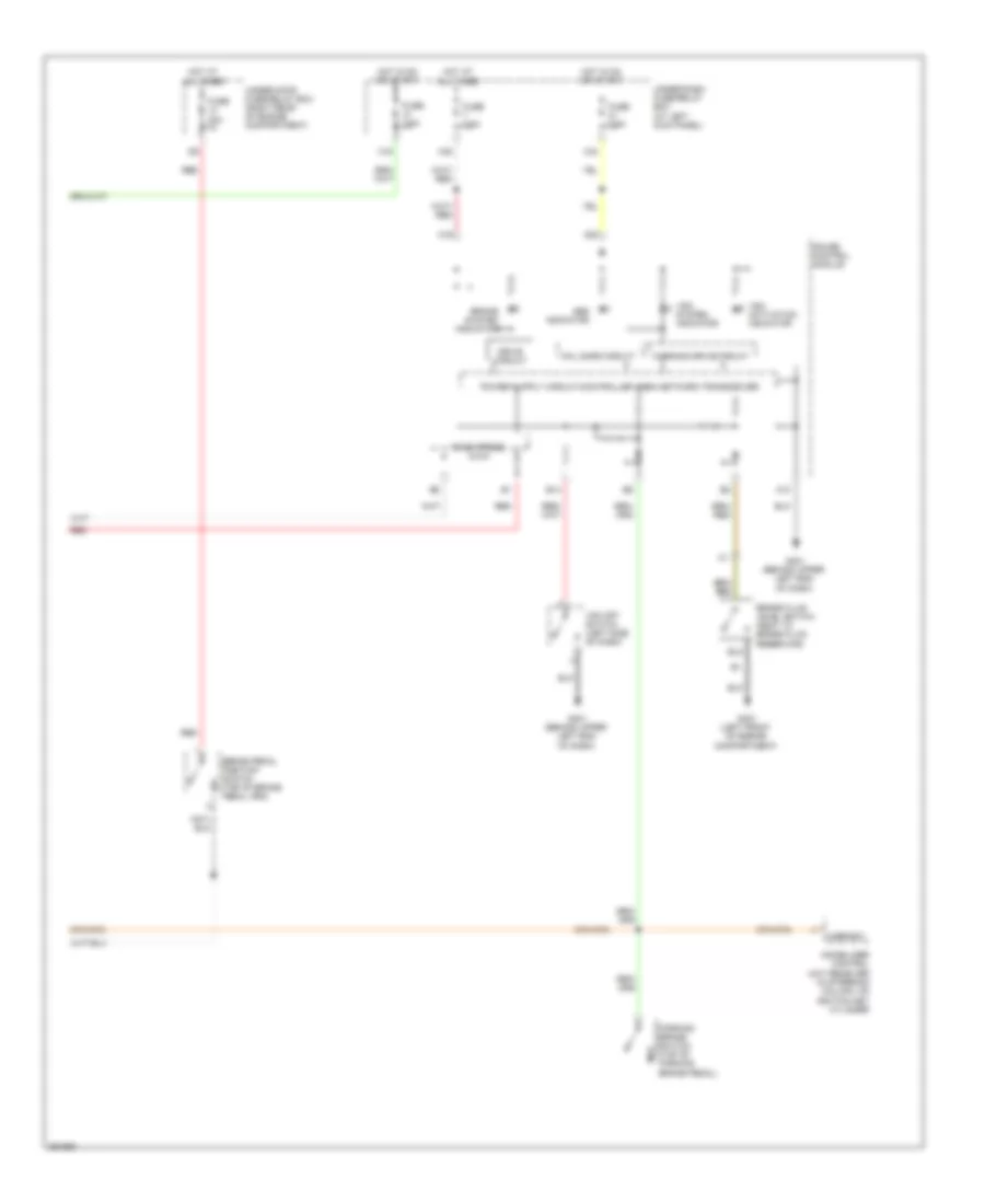
List of elements for Anti-lock Brakes Wiring Diagram (1 of 2) for Honda Ridgeline RT 2008:
- (behind right kick panel)
- (left side of engine compartment)
- +b-fsr
- +b-mr
- A36
- Auxiliary under-hood fuse box (left rear of engine compartment)
- Bksw
- Can-h
- Can-l
- Computer data lines system
- Fl+b
- Fl-gnd
- Flp
- Fr+b
- Fr-gnd
- Frp
- Fuse 20a
- Fuse 40a
- G302 (behind left side of front bumper)
- Gnd
- Hot at all times
- Ig1
- J/c c451 (under middle of dash)
- K-line
- Left front wheel speed sensor (left side of engine compt)
- Left rear wheel speed sensor (under rear of vehicle)
- Parbrk
- Pnk
- Powertrain control (pcm) module (right rear of engine compartment)
- Red
- Right front wheel speed sensor (right side of engine compt)
- Right rear wheel speed sensor (under rear of vehicle)
- Rl+b
- Rl-gnd
- Rlp
- Rr+b
- Rr-gnd
- Rrp
- S-gnd
- Sgnd
- Steering angle sensor (in steering column)
- Vsa modulator control unit
- Vtm-4 control unit
- Yaw rate-lateral acceleration sensor (under center console)
Anti-lock Brakes Wiring Diagram (2 of 2) for Honda Ridgeline RT 2008
List of elements for Anti-lock Brakes Wiring Diagram (2 of 2) for Honda Ridgeline RT 2008:
- A10
- A19
- A20
- Abs indicator
- B14
- Brake fluid level switch (next to brake fluid reservoir)
- Brake pedal position switch (top of brake pedal arm)
- Brake system indicator
- Drive circuit
- F-can trans
- Fail safe circuit
- Fuse 20a
- Fuse 7.5a
- G301 (left front of engine compartment)
- G401 (behind upper left end of dash)
- Gauge control module
- H/brksw
- Hot at all times
- Hot in on or start
- Immobilizer control unit receiver (in steering column, on ignition key cylinder
- Parking brake switch (top of parking brake pedal)
- Red
- Under-dash fuse/relay box (at left kick panel)
- Under-hood fuse/relay box (right rear of engine compartment)
- Vsa system indicator
- Vsa activation indicator
- Vsa off switch (left side of dash)
- Warning drive circuit
- X16
- X34
- X35