ANTI-LOCK BRAKES
Anti-lock Brake Wiring Diagrams for Land Rover Range Rover HSE 2000
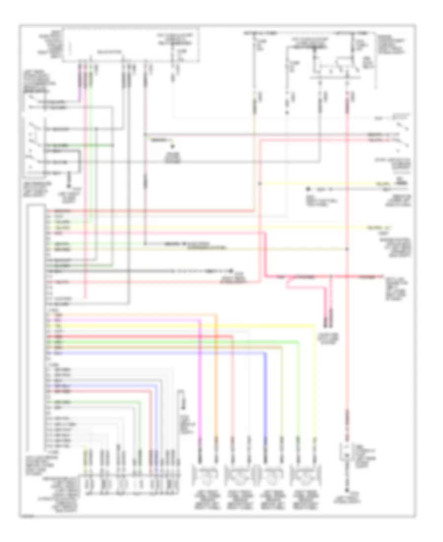
List of elements for Anti-lock Brake Wiring Diagrams for Land Rover Range Rover HSE 2000:
- (left front of eng compt)
- (left rear of eng compt, top of brake fluid reservoir) brake fluid level switch
- (right rear of eng compt)
- Abs booster unit 1-left front 2-right front 4-left rear 5-right rear 6-traction control 7-demanual (left rear of eng compt)
- Abs hydraulic pump (left rear of eng compt)
- Abs pressure switch unit (left side of eng compt)
- Abs pump relay
- Anti-lock brake system ecu (behind lower right side of dash)
- Body electrical control module (under right front seat)
- C0570
- C0571
- C0575
- C0637
- C1276
- C1288
- C1289
- C1584
- C1585
- C1586
- Computer data lines system
- Cruise control system
- Data link connector (obd ii) (at lower right side of dash)
- Electronic suspension system
- Engine compartment fuse box (right front of eng compt)
- Engine control module (ecm) (at left rear corner of eng compt)
- Fuse 10a
- Fuse 30a
- Fuse 5a
- G100
- G104 (left rear of eng compt)
- G105
- G203 (right footwell trim panel)
- Hot at all times
- Hot in run & start (when ignition relay energized)
- Hot in run & start (when rl10 relay energized)
- Left front wheel speed sensor (behind left front wheel)
- Left rear wheel speed sensor (behind left rear wheel)
- Maxi fuse 3 40a
- Nca
- Ohms
- Pnk
- Pnk/red
- Red
- Resistor (under left side of dash)
- Right front wheel speed sensor (behind right front wheel)
- Right rear wheel speed sensor (behind right rear wheel)
- Solid state
- Stop lamp switch (on brake support)
 English