ANTI-LOCK BRAKES
Anti-lock Brakes Wiring Diagram for Land Rover Range Rover HSE 2006
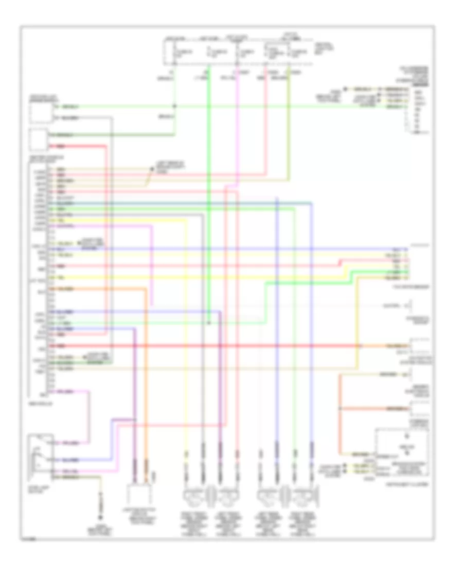
List of elements for Anti-lock Brakes Wiring Diagram for Land Rover Range Rover HSE 2006:
- (behind right kick panel)
- (left rear of engine compt) c0362
- (on underside of steering column) steering angle sensor
- Abs ind
- Abs module
- Bla
- Bls
- Braking system/ pad wear warning ind
- C0230
- C0233
- C0554 (behind left kick panel)
- C0580
- C0583
- C0587
- C2040
- C2114
- Can h+
- Can h-
- Can hi
- Can lo
- Can-h
- Can-l
- Center console switch pack
- Central junction box
- Computer data lines system
- Diag k
- Diagnostic socket
- Fuse 35 5a
- Fuse 38 5a
- Fuse 55 30a
- Fuse 9 5a
- Generic electronic module
- Gnd
- Hdc/high-low range switch
- Hid
- Hot at all times
- Hot in acc or on
- Hot in on
- Ign
- Instrument cluster
- Lat acc
- Left front wheel speed sensor (behind left front wheelwell)
- Left rear wheel speed sensor (below left rear wheelwell)
- Lighting switch
- M gnd
- Maxi fuse 63 50a
- Module
- Navigation system module
- Nca
- Pata
- Red
- Ref
- Right front wheel speed sensor (behind right front wheelwell)
- Right rear wheel speed sensor (below right rear wheelwell)
- Sig
- Speed out
- Steering lock ecu
- Stop lamp switch
- Test
- Ubmr
- Ubvr
- Vso
- Wpfl
- Wpfr
- Wprl
- Wprr
- Wsfl
- Wsfr
- Wsrl
- Wsrr
- Yaw rate sensor
 English