ANTI-THEFT
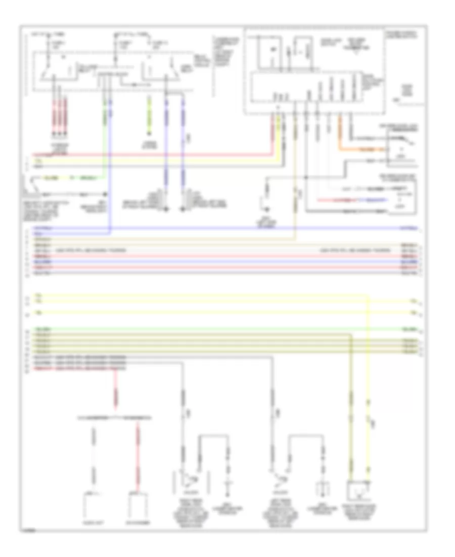
Forced Entry Wiring Diagram (1 of 3) for Honda Ridgeline SE 2014

List of elements for Forced Entry Wiring Diagram (1 of 3) for Honda Ridgeline SE 2014:
- (not used)
- (usa: rts, rtl, se; canada: touring)
- 20a
- 7.5a
- A10
- A19
- A20
- Anti-theft system
- As unlock
- B-can
- Body controller area network transceiver
- C408
- C453
- C454
- D11
- Door lock knob
- Door lock switch
- Dr unlock
- Driver's door switch (on left "b" pillar)
- Drswas
- Drswdr
- Drswra
- Drswrd
- E10
- E14
- E15
- Front passenger's door lock knob switch (usa: rts, rtl, se; canada: touring)
- Front passenger's door switch (on right "b" pillar)
- Front passenger's power window switch/door lock switch
- Fuse 21
- Fuse 2a
- Fuse 7.5a
- Fuse 8
- G401 (left side of dash)
- G402 (right end of dash)
- G403 (left side of dash)
- G501 (under center console)
- Gauge control module
- H10
- H12
- H13
- Hot at all times
- Hot in on or start
- Ig1
- Ignition key switch
- Ignition key switch/key light
- K11
- K12
- Left rear door switch (on left "c" pillar)
- Lock
- Micu
- Micu gnd
- Multi- information display (mid) unit
- N28
- N38
- N44
- P1 sg-1
- P13 ig key sw
- P25 rem as lock
- P27 scty in
- P29 sil as unlock
- P9 rem as unlock
- Q11 tailgate sw
- Q12 trunk handle sw
- Q2 sil ra unlock
- Q3 sil rd unlock
- Q4 trunk unlock
- Right rear door switch (on right "c" pillar)
- Security light ind (usa: rts, rtl, se; canada: touring)
- Trunk act
- Trunk sw
- Under-dash fuse/relay box (at left kick panel)
- Unlock
- Vbu
- Warning drive circuit
- X34
- X35
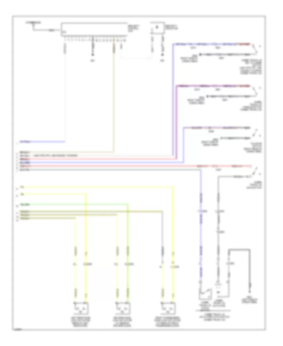
Forced Entry Wiring Diagram (2 of 3) for Honda Ridgeline SE 2014
List of elements for Forced Entry Wiring Diagram (2 of 3) for Honda Ridgeline SE 2014:
- (usa: rts, rtl, se; canada: touring)
- 15a
- 20a
- 7.5a
- A18
- Audio unit
- C203
- C454
- C506
- C507
- Cd changer
- Control block
- Door lock knob
- Door lock switch
- Door multiplex control unit
- Driver's door key cylinder switch
- Driver's door lock knob switch
- Fuse 13
- Fuse 4
- Fuse 7
- G201 (behind right headlight)
- G401 (left side of dash)
- G501 (under center console)
- H14
- H15
- High horn (behind left side of front bumper)
- Horn relay
- Horns system
- Hot at all times
- Ign
- Interior lights system
- Key
- Key lock
- Key unlock
- Keyless entry transmitter
- Knob lock
- Knob unlock
- Left rear door lock knob switch (usa: rts, rtl, se; canada: touring) (rear of left rear door)
- Lock
- Low horn (behind left end of front bumper)
- Pg1
- Power window master switch
- Relay control module
- Right rear door lock actuator (rear of right rear door)
- Right rear door lock knob switch (usa: rts, rtl, se; canada: touring) (rear of right rear door)
- Security hood switch (usa: rts, rtl, se; canada: touring) (center front of engine compt)
- Sgnd
- Taillight relay
- Under-hood fuse/relay box (at right rear of engine compt)
- Unlock
- Vbu
- W/ navigation
- W/o navigation
Forced Entry Wiring Diagram (3 of 3) for Honda Ridgeline SE 2014
List of elements for Forced Entry Wiring Diagram (3 of 3) for Honda Ridgeline SE 2014:
- (usa: rts, rtl, se; canada: touring)
- C403
- C408
- C453
- C506
- C509
- C510
- C601
- Driver's door lock actuator (at rear of driver's door)
- Front passenger's door lock actuator (at rear of front passenger's door)
- G51
- G601 (left side of cargo area)
- G602 (right side of cargo area)
- In-bed trunk lid actuator
- In-bed trunk lid actuator/latch switch (in-bed trunk lid)
- In-bed trunk lid handle switch (in-bed trunk lid)
- In-bed trunk lid key cylinder switch (usa: rts, rtl, se; canada: touring) (in-bed trunk lid)
- In-bed trunk lid latch switch
- In-bed trunk lid main switch
- Left rear door lock actuator (rear of left rear door)
- Mic
- Microphone
- Nca
- Security control unit
- Security indicator
- Tailgate switch (right rear of cargo area)
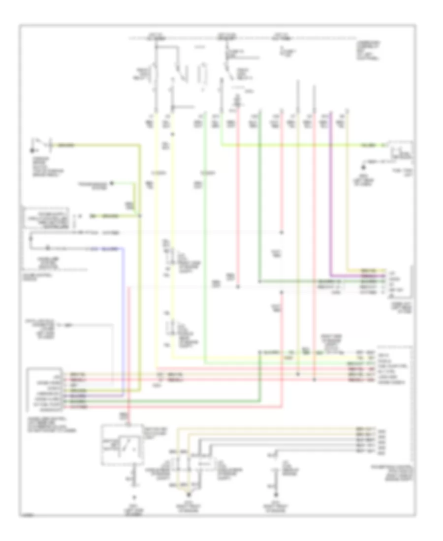
Immobilizer Wiring Diagram for Honda Ridgeline SE 2014
List of elements for Immobilizer Wiring Diagram for Honda Ridgeline SE 2014:
- (lower left side of dash)
- (right side of engine compt) j/c c101
- +b backup
- A11
- A19
- A41
- A46
- B21
- B23
- B40
- B41
- B42
- C18
- C204
- C205
- C402
- C41
- Data link (dlc) connector
- Diag-h
- E12
- E13
- Fuel pump
- Fuel pump ctrl
- Fuel tank unit
- Fuse 19 15a
- Fuse 7 7.5a
- G101 (right front of engine)
- G401 (left side of dash)
- G502 (left rear of cabin)
- Gauge control module
- Gnd
- H/brake sw
- Hot at all times
- Hot in on or start
- Ig key sw
- Ig1
- Ig1 fuel pump
- Ign in
- Ignition key switch
- Ignition key switch/key light
- Immobi alarm
- Immobi code
- Immobi code in
- Immobilizer control unit receiver (in steering column, on ignition key cylinder)
- Immobilizer system indicator
- Imocd
- Imoes unit (left rear of cab)
- J/c c101 (right side of engine compt)
- J/c c103 (middle rear of engine compt)
- J/c c104 (middle rear of engine compt)
- J/c c105 (rear of engine)
- Key sw
- Lg1
- Lg3
- Logic gnd
- Micu
- P13
- Parking brake switch (top of parking brake pedal)
- Pgm-fi main relay 1
- Pgm-fi main relay 2
- Powertrain control (pcm) module (right side of engine compt)
- Pwr in
- Rly ctrl
- Transmissions system
- Under-dash fuse/relay box (at left kick panel)
- X35
- X38