BODY COMPUTER
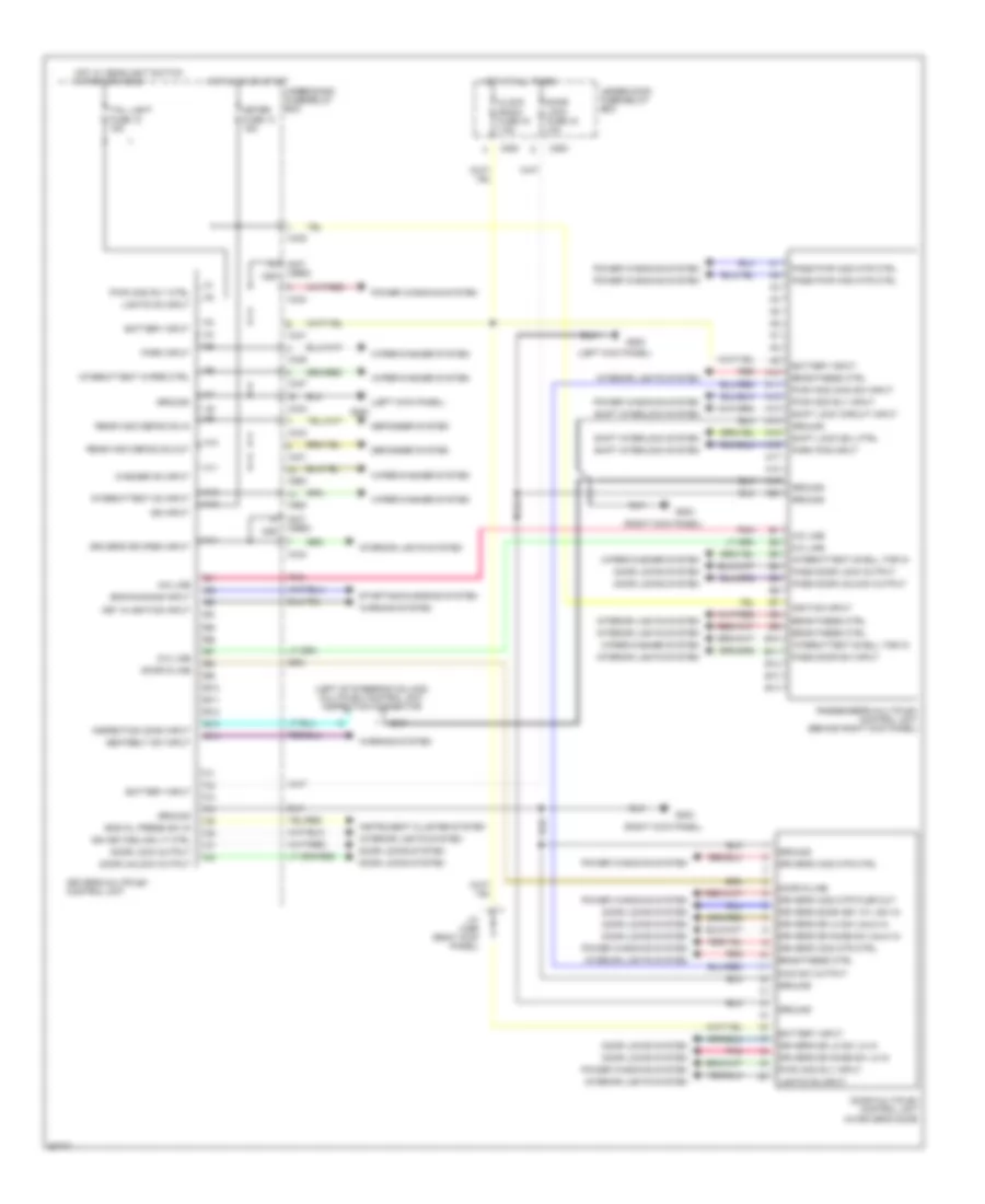
Multiplex Control Wiring Diagram for Honda Prelude 1998
List of elements for Multiplex Control Wiring Diagram for Honda Prelude 1998:
- (left kick panel)
- (left of steering column) multiplex control unit inspection connector
- (not used) c551
- (right kick panel)
- A-d line
- A10
- A11
- A12
- A13
- A14
- A15
- A16
- A17
- A18
- A19
- A20
- B10
- B11
- B12
- B13
- B14
- Battery input
- Brightness ctrl
- C254
- C431
- C432
- C433
- C434
- C436
- C437
- C980
- Clock radio fuse 43 7.5a
- D-a line
- Defogger system
- Door d-line
- Door lock fuse 44 10a
- Door lock output
- Door locks system
- Door multiplex control unit (in driver's door)
- Door unlock output
- Driver's door key cyl sw in
- Driver's dr knob sw lk in
- Driver's dr knob sw unlk in
- Driver's dr lk sw lk in
- Driver's dr lk sw unlk in
- Driver's dr open input
- Driver's multiplex control unit
- Driver's wdo mtr ctrl
- Driver's wdo mtr plsr out
- Eng oil press sw in
- Eng running input
- G200
- G203
- Ground
- Hot at all times
- Hot in on or start
- Hot w/ headlight switch in park or head
- Ign input
- Ign key/ceiling lt ctrl
- Ignition input
- Inspection conn input
- Instrument cluster system
- Interior lights system
- Intermittent dwell tmr in
- Intermittent on input
- Intermittent wiper ctrl
- J/c c456 (right kick panel)
- Key in ignition input
- Lights on input
- Main sw output
- Meter fuse 13 15a
- Park input
- Park pos input
- Pass door lock output
- Pass door sw input
- Pass door unlock output
- Pass pwr wdo mtr ctrl
- Passenger's multiplex control unit (behind right kick panel)
- Pnk
- Power windows system
- Pwr wdo main sw input
- Pwr wdo rly ctrl
- Pwr wdo rly input
- Rear wdo defog on in
- Rear wdo defog on out
- Red
- Seatbelt sw input
- Shift interlock system
- Shift lock circuit input
- Shift lock sol ctrl
- Starting/charging system
- Tail light fuse 10 15a
- Under-dash fuse/relay box
- Under-hood fuse/relay box
- Warning system
- Washer on input
- Wiper/washer system
 English