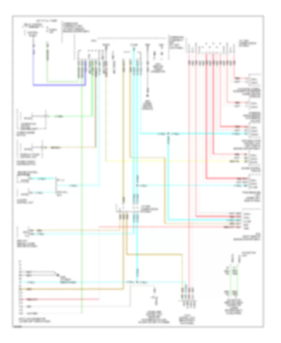
COMPUTER DATA LINES
Computer Data Lines Wiring Diagram for Honda Ridgeline RT 2008
List of elements for Computer Data Lines Wiring Diagram for Honda Ridgeline RT 2008:
- (if equipped)
- (not used)
- A24
- A31
- A36
- A42
- A43
- B-can
- B10
- B19
- C11
- Can-h
- Can-l
- Chk
- Climate control unit
- Combination switch control unit
- Control block
- D10
- D11
- Data link connector (lower left side of dash)
- Diag (+)
- Diag (-)
- Diag-h
- Diag-k
- Door multiplex control unit
- Fuse 8 15a
- G402 (at right side of dash)
- G501 (under center console)
- Gauge control module
- Gnd
- Heater control unit-panel
- Hot at all times
- Immobilizer control unit receiver (in steering column, on ignition key cylinder)
- J/c c451 (under middle of dash)
- J/c c452 (under middle of dash)
- K-line
- Micu
- Micu service check connector
- N10
- N13
- N14
- N22
- N28
- Navigation service check connector (under driver's seat)
- Navigation unit
- Pcm (right rear of engine compartment)
- Power window master switch
- Red
- Red a22
- Relay control module
- Rt, lx
- Rts, rtl, ex-l
- Scs
- Side of dash)
- Srs unit (behind lower center of dash)
- Steering angle sensor (in steering column)
- Tpms receiver unit (under left
- Under-dash fuse/relay box (at left kick panel)
- Under-hood fuse/relay box (at right rear of engine compartment)
- Vsa modulator control unit (left side of engine compartment)
- Vtm-4 control unit (behind right kick panel)
- Wen
- Wiper/washer switch
- X18
- X27
- Yaw rate-lateral acceleration sensor (under center console)
 English