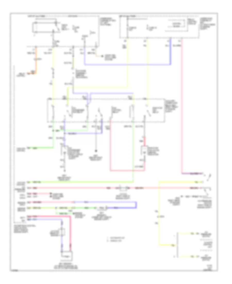
COOLING FAN
Cooling Fan Wiring Diagram for Honda Ridgeline RTS 2014
List of elements for Cooling Fan Wiring Diagram for Honda Ridgeline RTS 2014:
- (right rear of engine compt)
- A/c condenser fan motor (front middle of engine compt)
- A/c condenser fan relay
- A/c diode assembly (behind glove box)
- A/c pressure switch
- A/c pressure switch (right side of engine compt)
- A20
- A21
- A37
- A48
- A49
- Automatic a/c
- Auxiliary under-hood relay box (right front of engine compt)
- B-can
- B34
- Block
- C14
- C204
- C251
- C32
- Can-h
- Can-l
- Climate control unit
- Computer data lines system
- Control
- D11
- D16
- Ect sensor 1 (at rear of engine, on top of water passage)
- Ect sensor 2 (under left side of engine compt)
- Ect1
- Engine controls system
- Fan control relay
- Fuse 10a
- Fuse 19 30a
- Fuse 20 30a
- Fuse 7.5a
- G201 (behind right headlight)
- G202
- High fan control
- Hot at all times
- Hot in on
- Hvac unit control
- J/c c101 (right side of engine compt)
- J/c c105 (rear of engine)
- Low fan control
- Manual a/c
- Micu
- N28
- Pgm-fi main relay 1
- Pnk
- Powertrain control module (pcm) (right side of engine compt)
- Radiator fan motor (behind radiator)
- Radiator fan relay
- Red
- Relay control
- Relay control module
- Sensor ground
- Sensor input
- Sg1
- Under-dash fuse/relay box (at left kick panel)
- Under-hood fuse/relay box (at right rear of engine compt)
 English