Čeština
 Dansk
Dansk Deutsch
 Ελληνικά
 English
 Español
 Suomi
Suomi Français
 Français
 עברית
עברית Hrvatski
 Magyar
 Italiano
 日本語
日本語 한국어
한국어 Nederlands
 Polski
 Português
 Português
 Română
 Русский
 Slovenčina
 Slovenščina
 Svenska
 Türkçe
 中文 (中国)

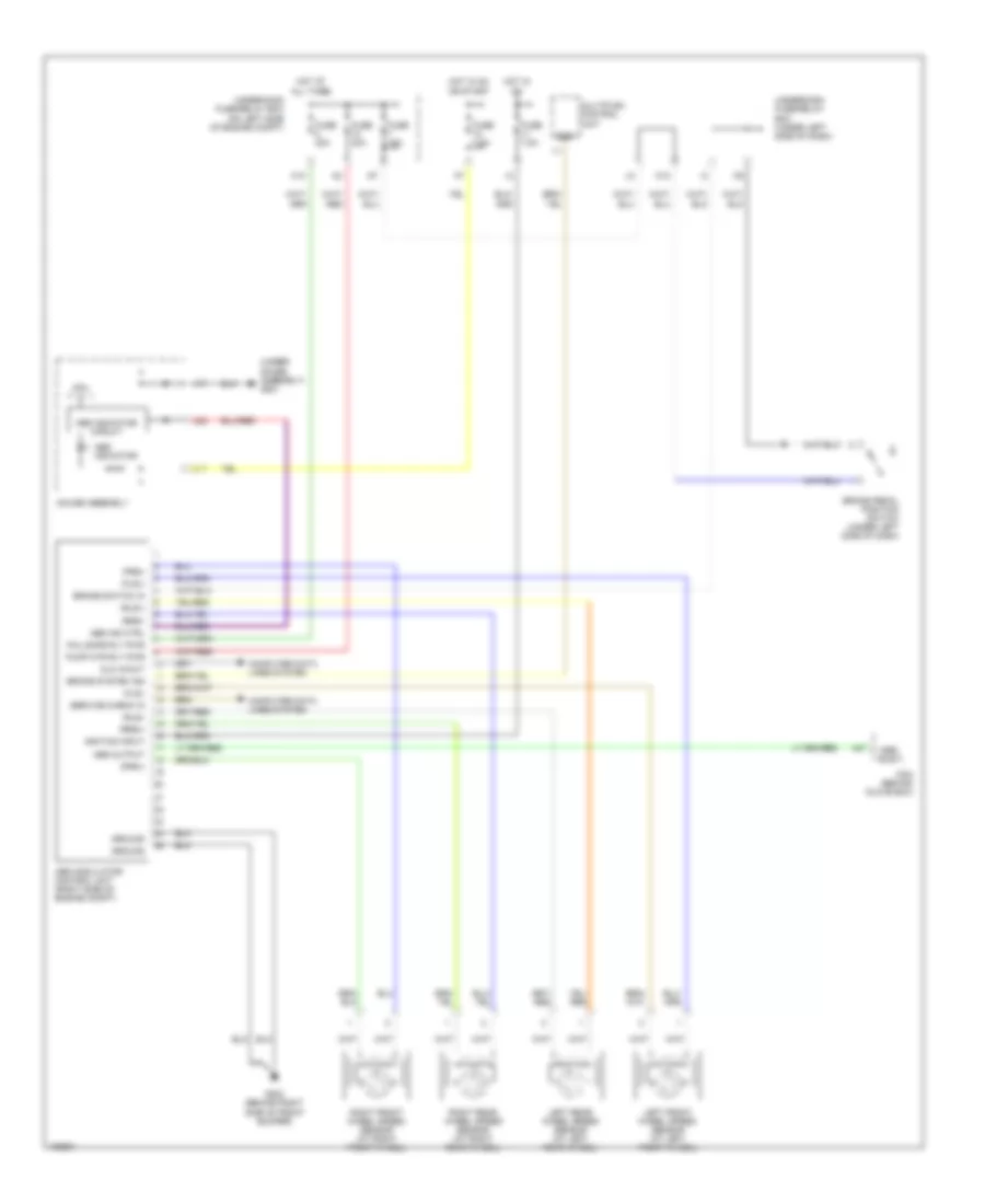
СИСТЕМА АНТИБЛОКИРОВОЧНОЙ ТОРМОЗНОЙ СИСТЕМЫ ABS
Электросхема антиблокировочной тормозной системы АБС (ABS), кроме хэтчбека и гибрида для Honda Civic 2004


Электросхема антиблокировочной тормозной системы АБС (ABS), кроме хэтчбека и гибрида для Honda Civic 2004 - Список элементов:
Электросхема антиблокировочной тормозной системы АБС (ABS), хэтчбек для Honda Civic 2004
Электросхема антиблокировочной тормозной системы АБС (ABS), хэтчбек для Honda Civic 2004 - Список элементов:
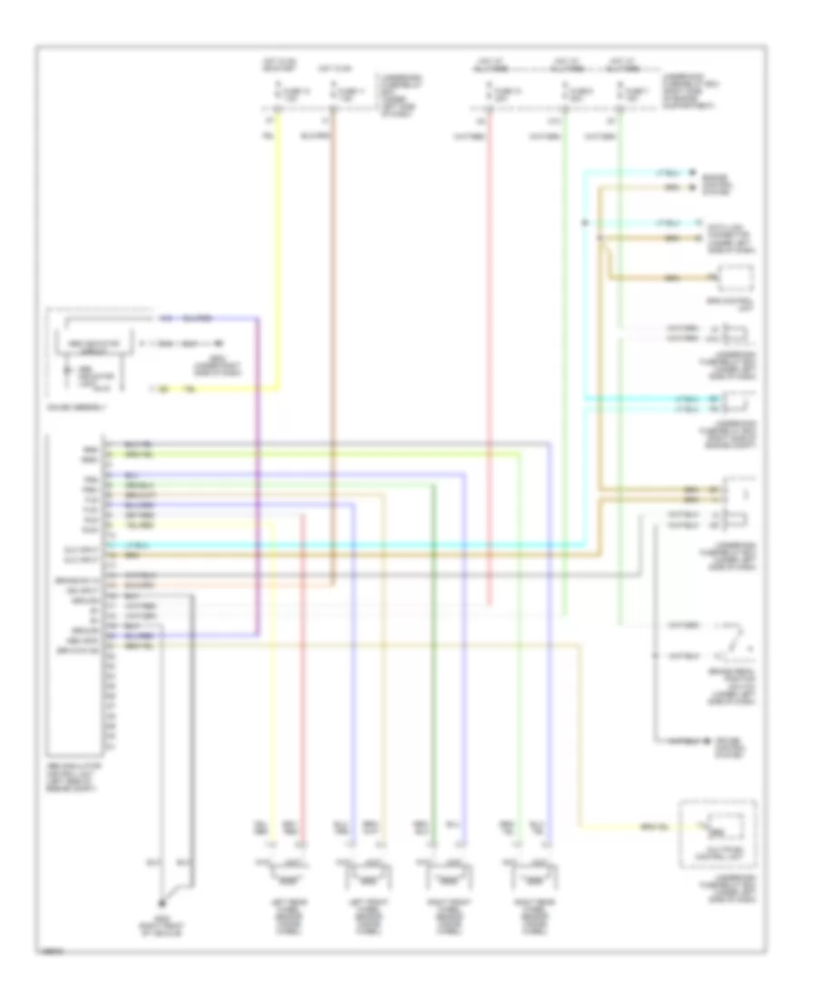
Электросхема антиблокировочной тормозной системы АБС (ABS), гибрид для Honda Civic 2004
Электросхема антиблокировочной тормозной системы АБС (ABS), гибрид для Honda Civic 2004 - Список элементов: