ENGINE PERFORMANCE
2.0L HYBRID
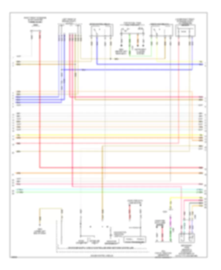
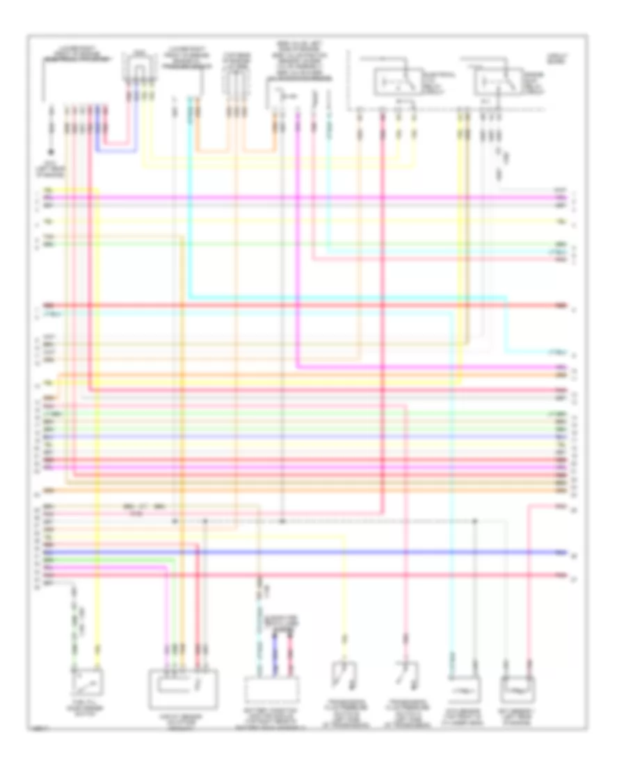
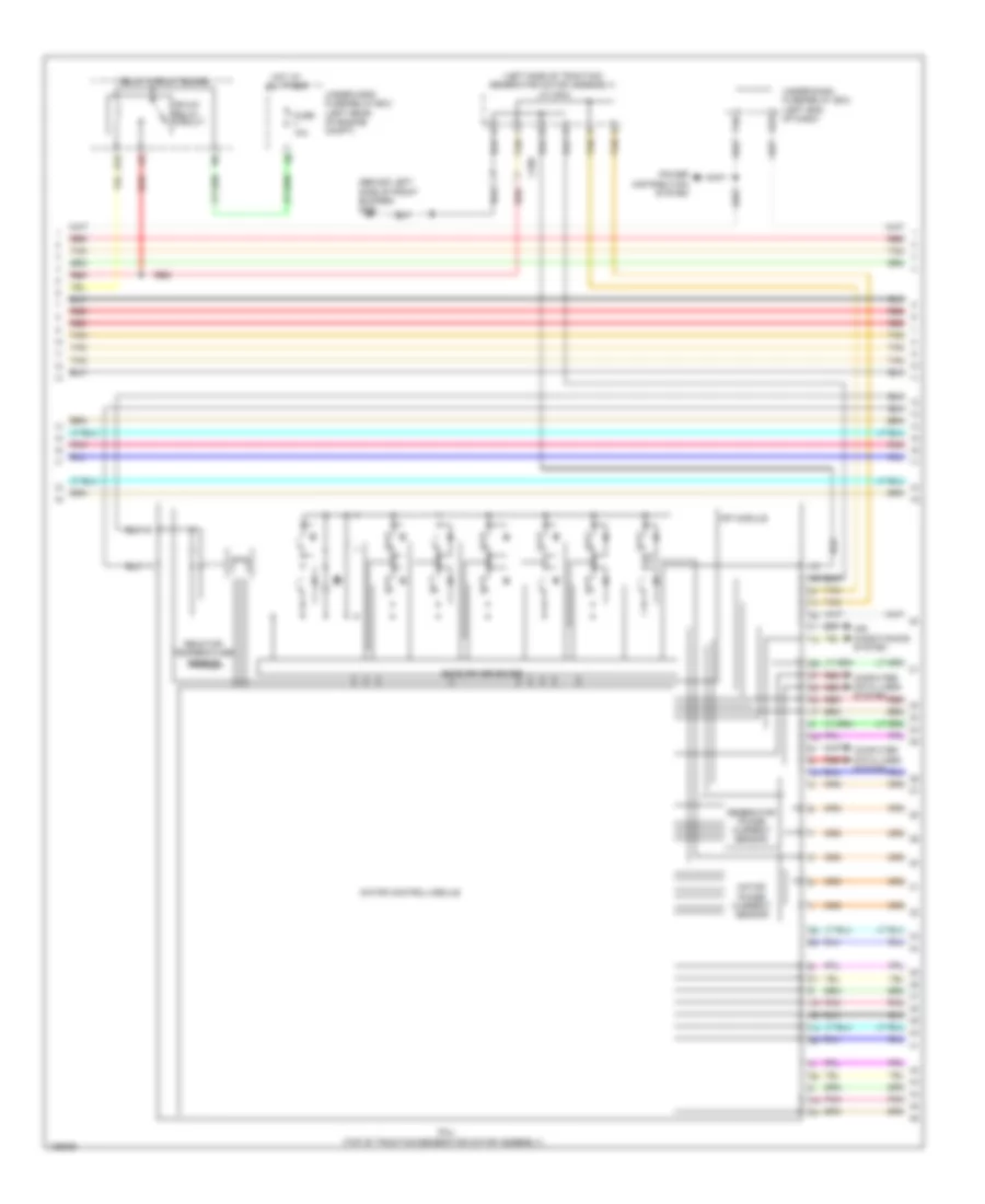
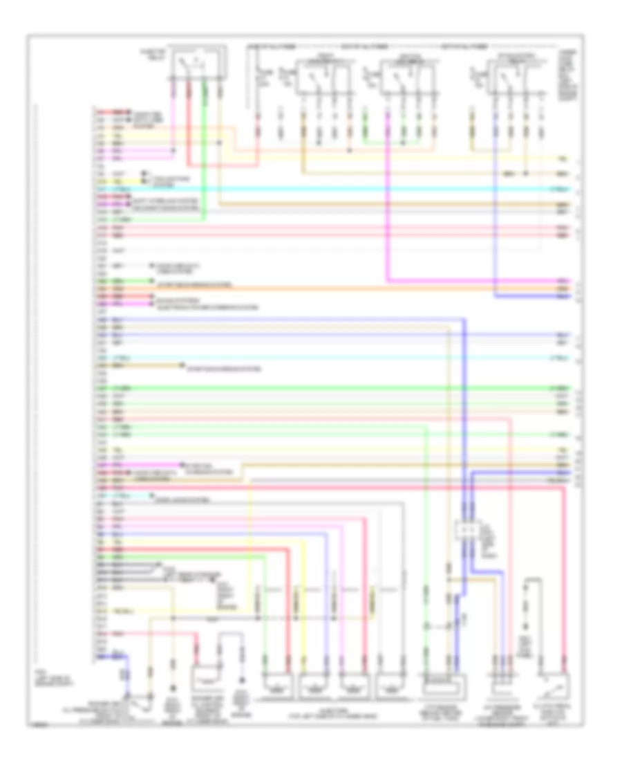
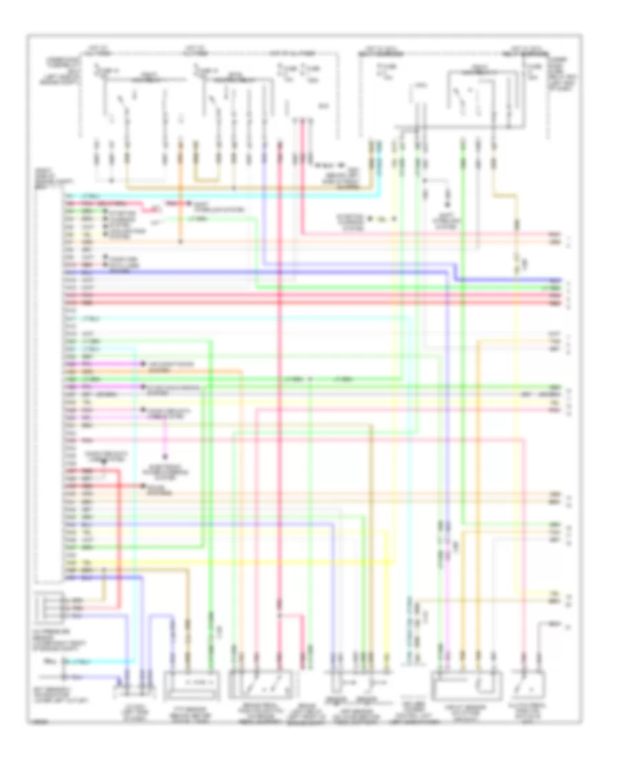
2.0L Hybrid, Engine Controls Wiring Diagram, Except Plug-In Hybrid (1 of 6) for Honda Accord Plug-In 2014

List of elements for 2.0L Hybrid, Engine Controls Wiring Diagram, Except Plug-In Hybrid (1 of 6) for Honda Accord Plug-In 2014:
- A10
- A11
- A12
- A13
- A14
- A15
- A16
- A17
- A18
- A19
- A20
- A21
- A22
- A23
- A24
- A25
- A26
- A27
- A28
- A29
- A30
- A31
- A32
- A33
- A34
- A35
- A36
- A37
- A38
- A39
- A40
- A41
- A42
- A43
- A44
- A45
- A46
- A47
- A48
- A49
- A50
- A51
- Anti-lock brakes system
- App sensor (on accelerator pedal support)
- App sensor a
- App sensor b
- C102
- C110
- C112
- C127
- C128
- C203
- Computer data lines system
- Cooling fans system
- Door locks system
- Ect sensor 2 (on radiator lower left outlet)
- Evap canister vent shut valve (under middle rear of vehicle, on evap control canister)
- Ftp sensor (behind center of fuel tank)
- Fuse 10a
- Fuse 15a
- Fuse 2-3 20a
- Fuse 20a
- Fuse 7.5a
- G101 (left rear of engine)
- Hot at all times
- Pcm (left front of engine compt)
- Pgm-fi main relay 1
- Pgm-fi sub relay
- Pnk
- Red
- Rfc relay
- Shift interlock system
- Shift solenoid valve a (left side of transmission)
- Shift solenoid valve b (left side of transmission)
- Under- hood fuse/ relay box (left rear of engine compt)
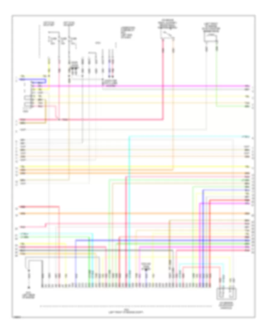
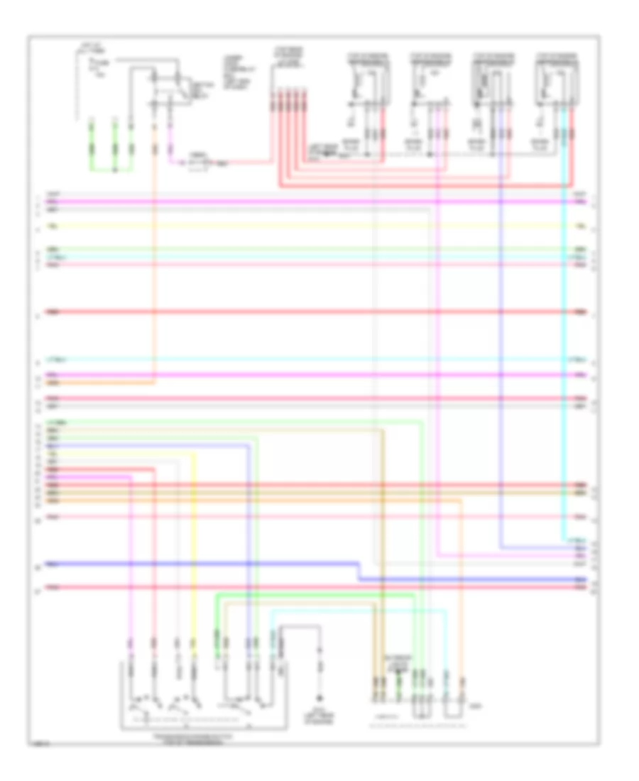
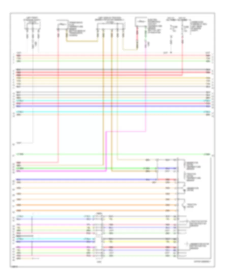
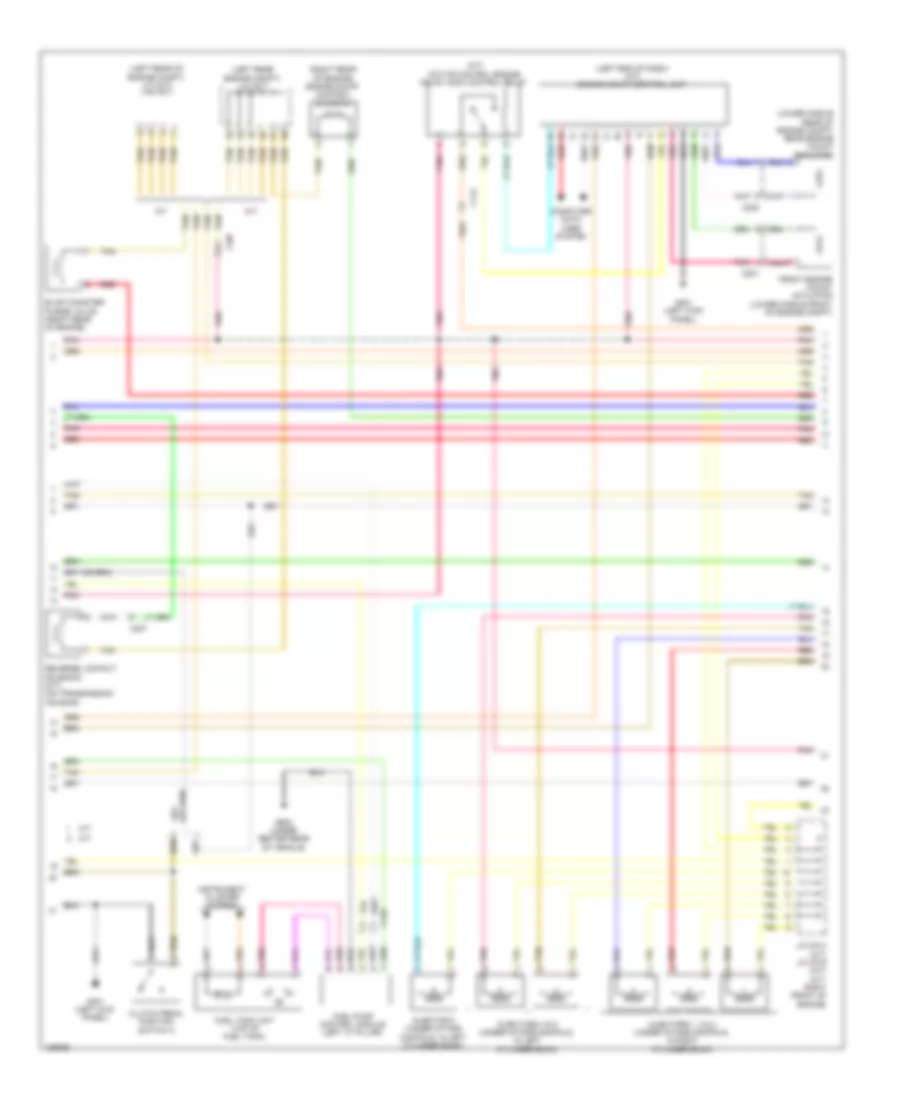
2.0L Hybrid, Engine Controls Wiring Diagram, Except Plug-In Hybrid (2 of 6) for Honda Accord Plug-In 2014
List of elements for 2.0L Hybrid, Engine Controls Wiring Diagram, Except Plug-In Hybrid (2 of 6) for Honda Accord Plug-In 2014:
- (left front of engine compt) j/c c012
- (lower right front of engine compt) a/c pressure sensor
- (right front of engine) evap canister purge valve 2
- (top of fuel tank) fuel tank unit
- A17
- A19
- A20
- C127
- C203
- C204
- C207
- Computer data lines system
- Dc-dc converter
- Etcs control relay
- F-can h
- F-can l
- F-can transceiver
- G502 (upper left end of dash)
- G602 (behind left rear seat)
- Gauge control module
- Indicator drive circuit
- Instrument cluster system
- Malfunction indicator lamp (mil)
- Pcu (top of traction/ generator motor assembly)
- Pgm-fi main relay 2
- Pnk
- Red
- Secondary ho2s (sensor 2) (in exhaust, downstream of catalytic converter)
- Stabilize circuit
- Tan
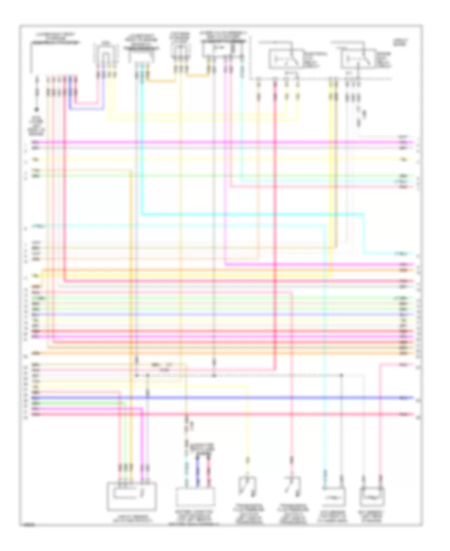
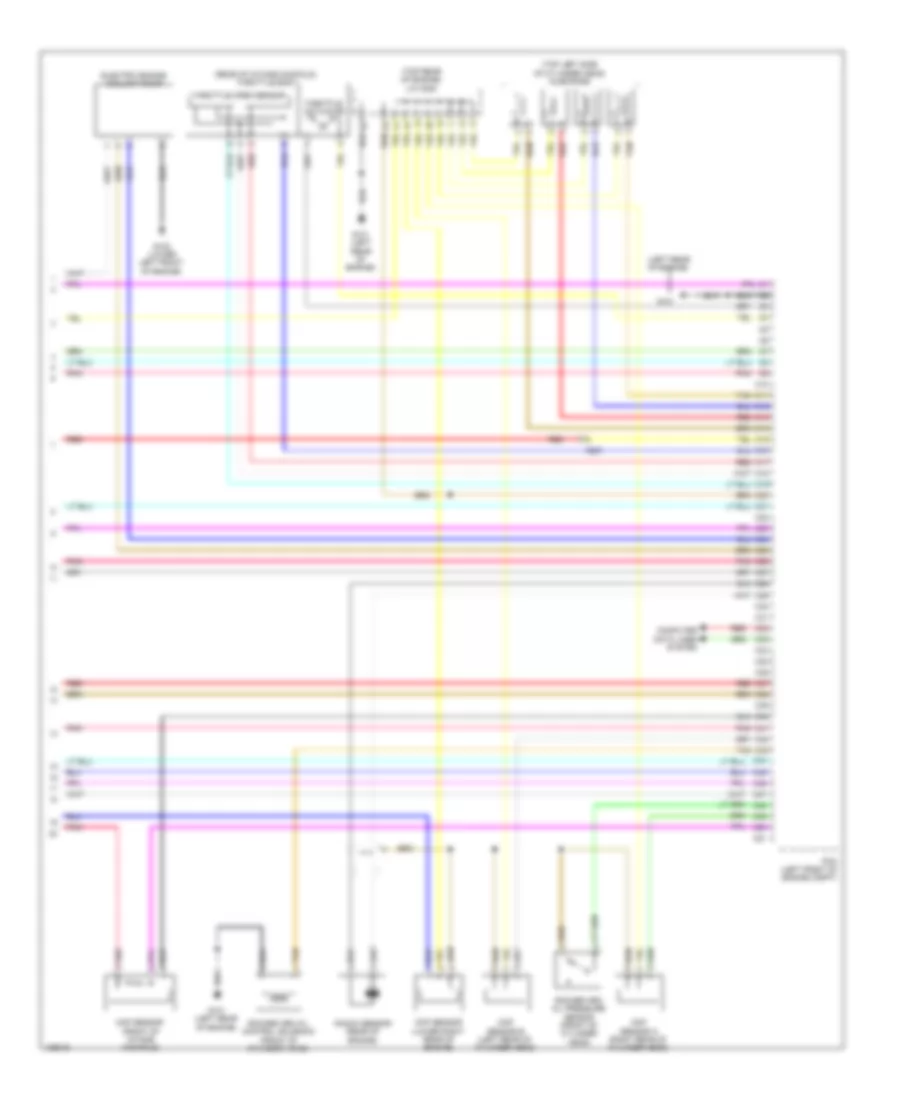
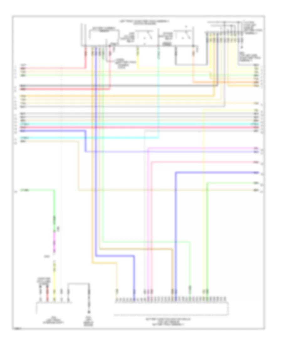
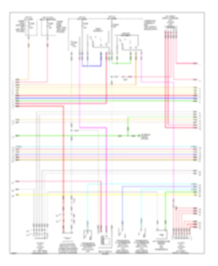
2.0L Hybrid, Engine Controls Wiring Diagram, Except Plug-In Hybrid (3 of 6) for Honda Accord Plug-In 2014
List of elements for 2.0L Hybrid, Engine Controls Wiring Diagram, Except Plug-In Hybrid (3 of 6) for Honda Accord Plug-In 2014:
- (left front of engine) evap canister purge valve
- (on brake pedal support) brake pedal position switch
- A/f sensor (on exhaust manifold)
- B10
- B11
- B12
- B13
- B14
- B15
- B16
- B17
- B18
- B19
- B20
- B21
- B22
- B23
- B24
- B25
- B26
- B27
- B28
- B29
- B30
- B31
- B32
- B33
- B34
- B35
- B36
- B37
- B38
- B39
- B40
- B41
- B42
- B43
- B44
- B45
- B46
- B47
- B48
- B49
- B50
- B51
- C201
- C203
- Computer data lines system
- Cooling fans system
- Door locks system
- E11
- E17
- E23
- F11
- Fuse 10a
- Fuse 15a
- Fuse 20a
- G101 (left rear of engine)
- Hot in on or start
- M10
- M11
- M12
- Micu
- Pcm (left front of engine compt)
- Pnk
- R10
- Red
- Tan
- Under-dash fuse/relay box (left end of dash)
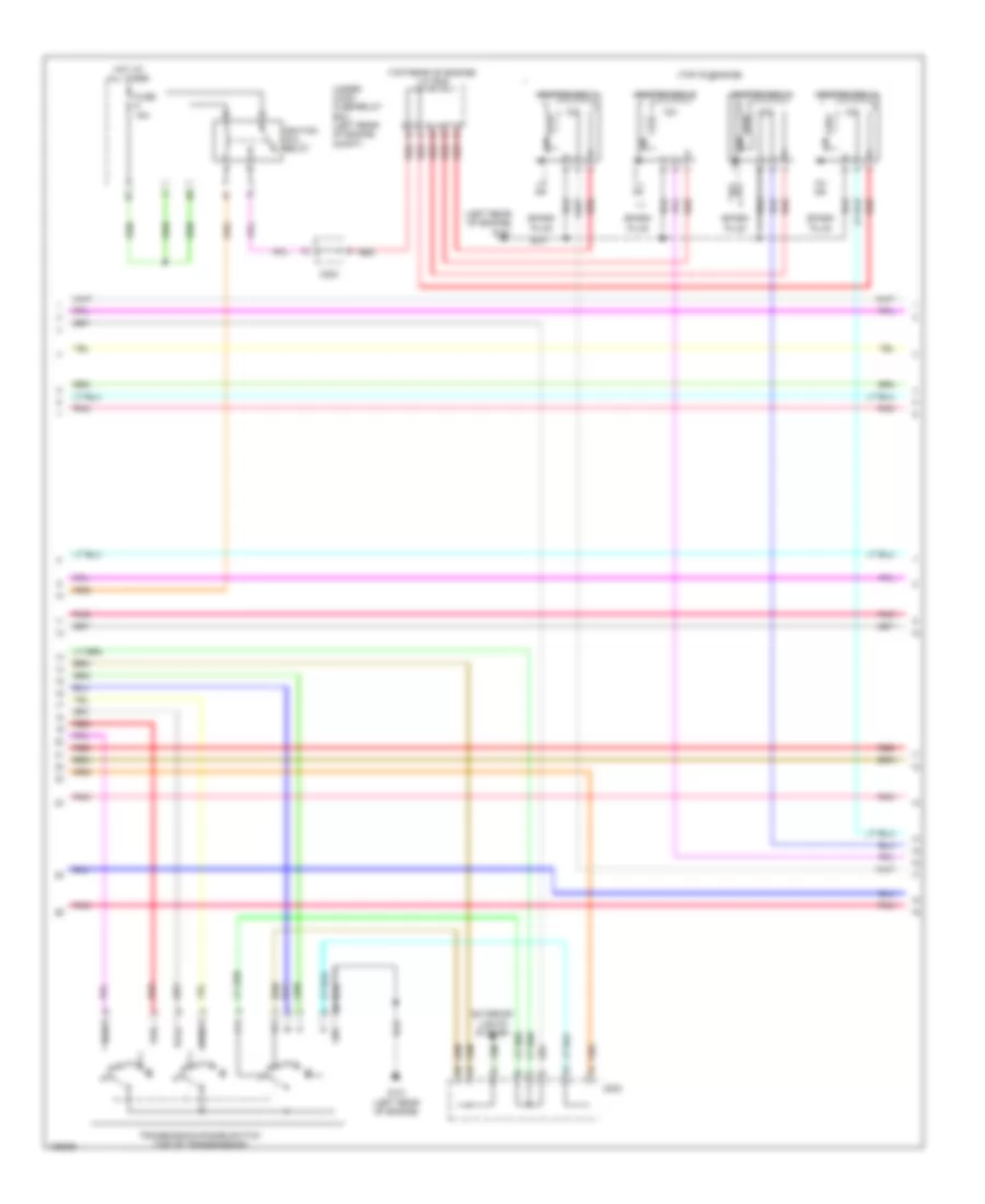
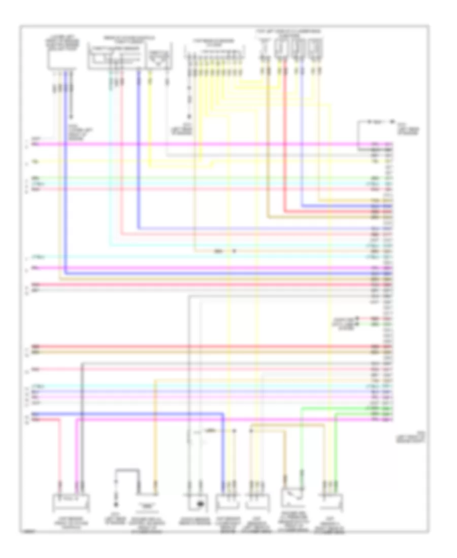
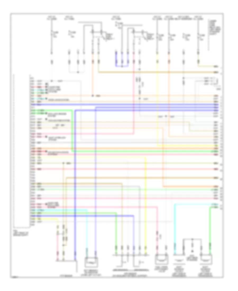
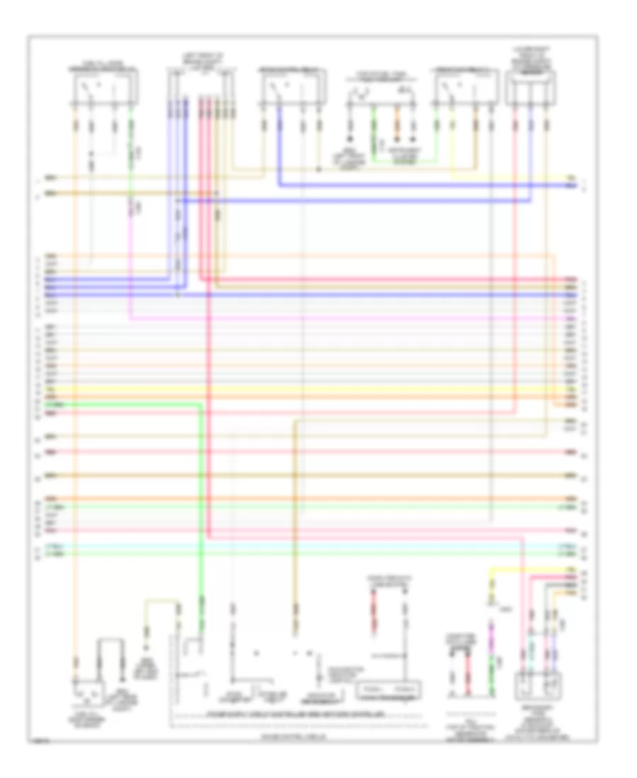
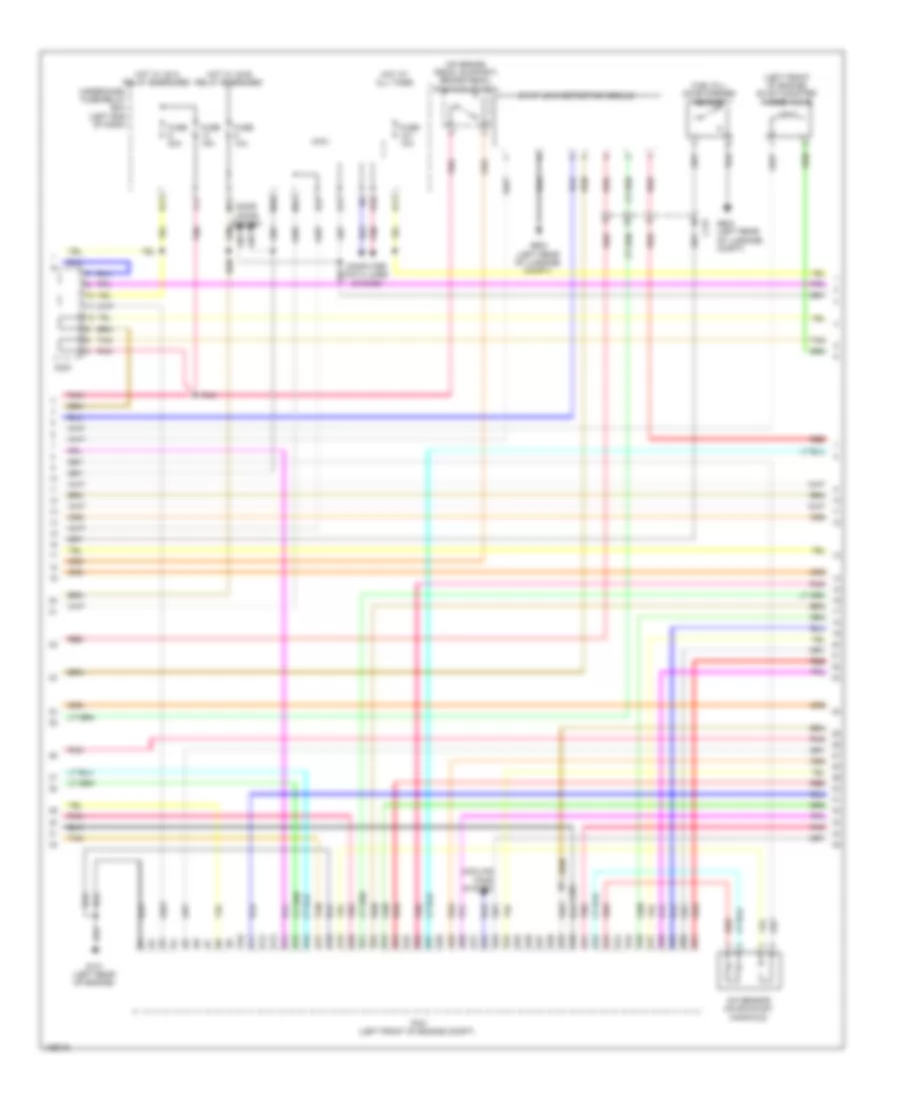
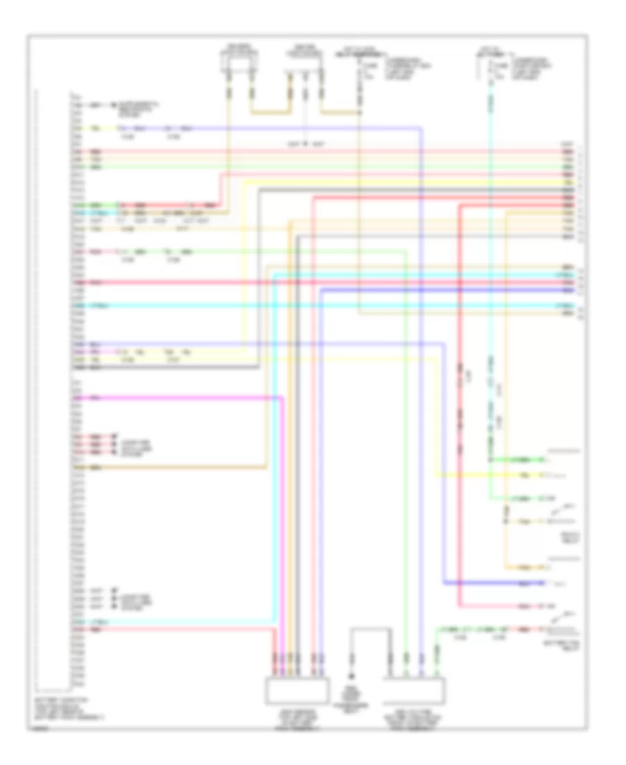
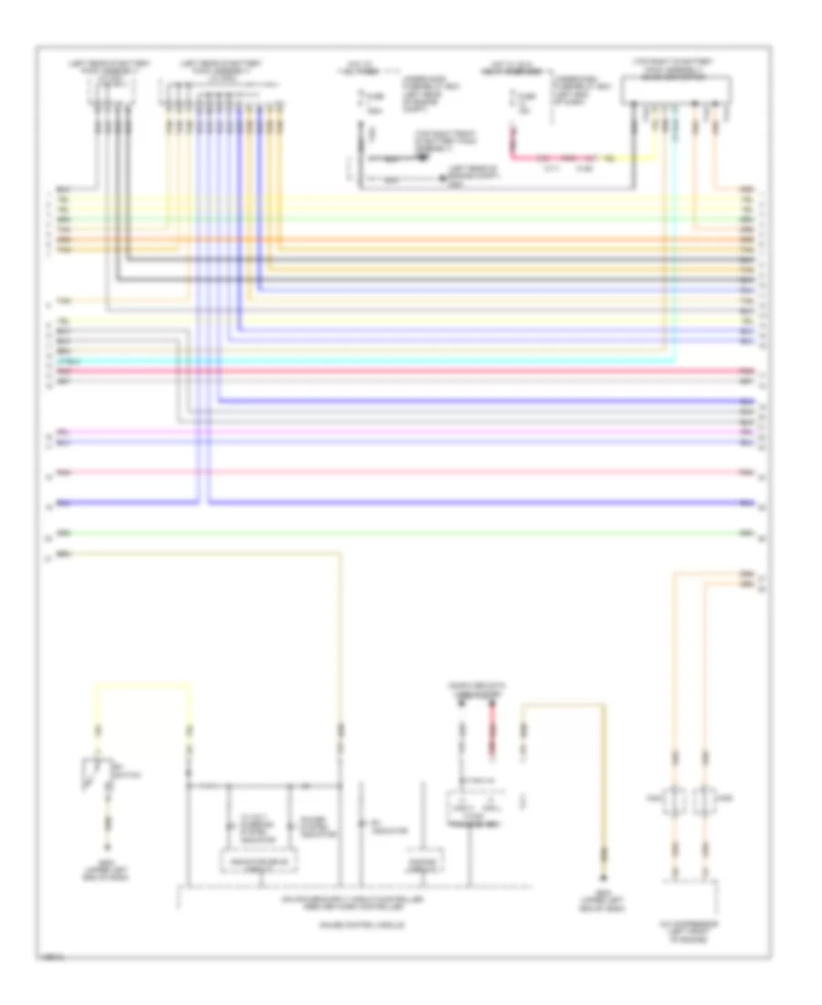
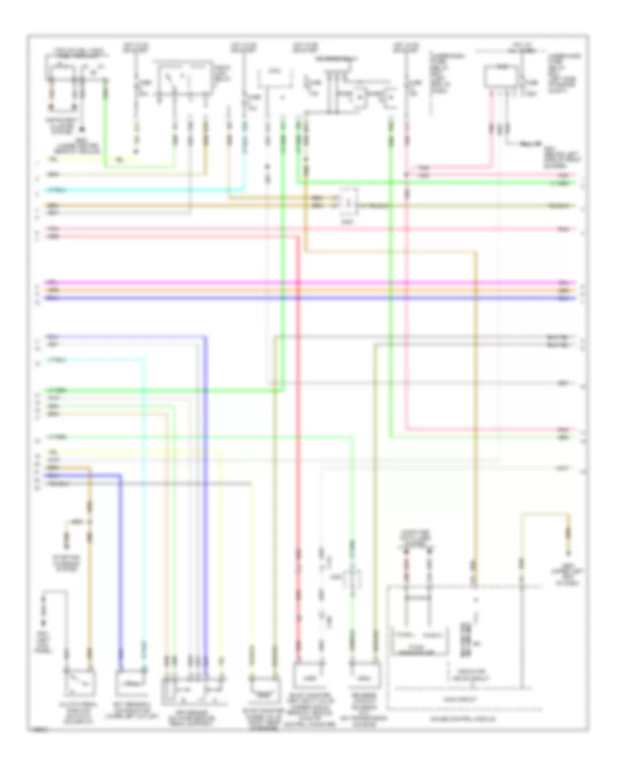
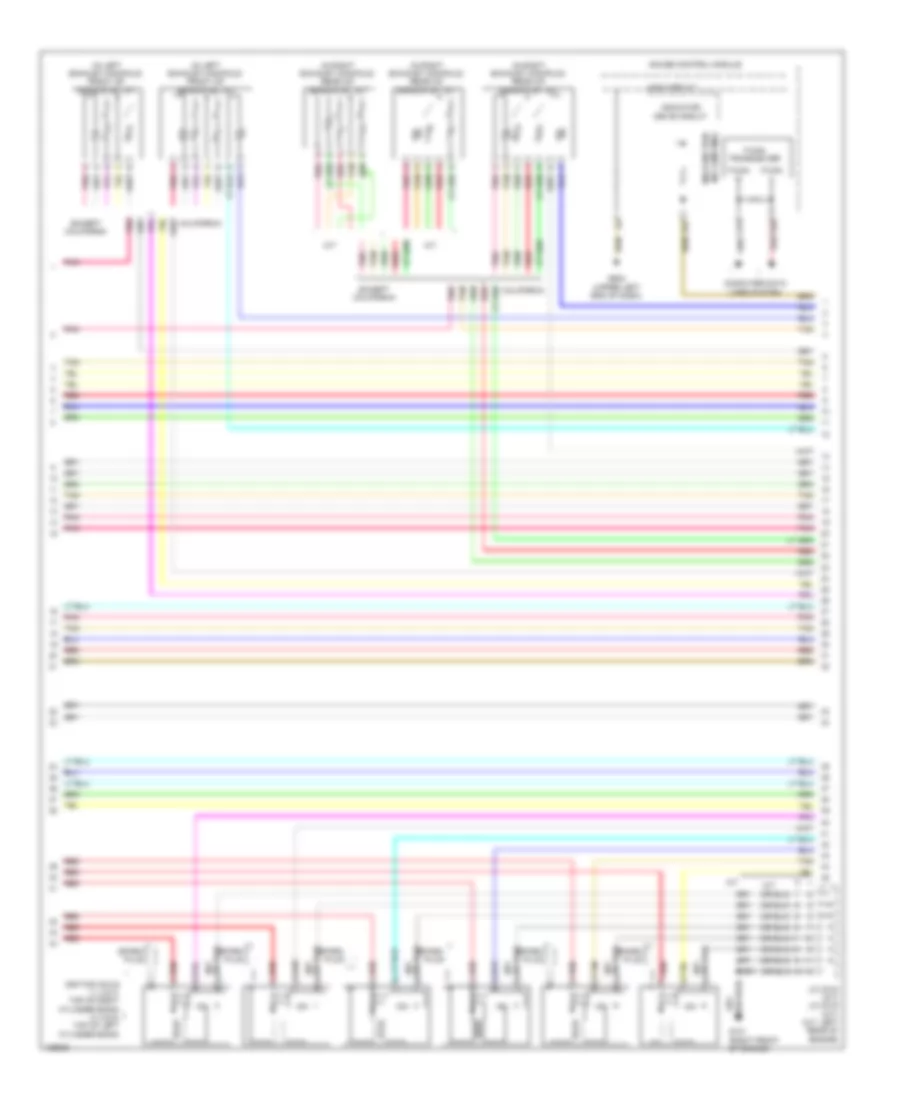
2.0L Hybrid, Engine Controls Wiring Diagram, Except Plug-In Hybrid (4 of 6) for Honda Accord Plug-In 2014
List of elements for 2.0L Hybrid, Engine Controls Wiring Diagram, Except Plug-In Hybrid (4 of 6) for Honda Accord Plug-In 2014:
- (in egr valve assembly) egr valve & egr valve position sensor
- (lower right front of engine) electrical vtc motor
- (lower right front of engine) engine oil pressure sensor
- (top rear of engine) j/c c005
- A13
- Battery condition monitor module (top left rear of battery pack assembly)
- C10
- C130
- C132
- C203
- C206
- C30
- C403
- Circuit board
- Computer data lines system
- Ect sensor 1 (left rear of engine)
- Electrical vtc relay circuit
- Engine ewp relay circuit
- G102 (lower left front of engine)
- Inta sensor (top front of cylinder head)
- Maf/iat sensor (on intake air duct)
- Pnk
- Red
- Tan
- Transmission fluid pressure switch a (left side of transmission)
- Transmission fluid pressure switch b (left side of transmission)
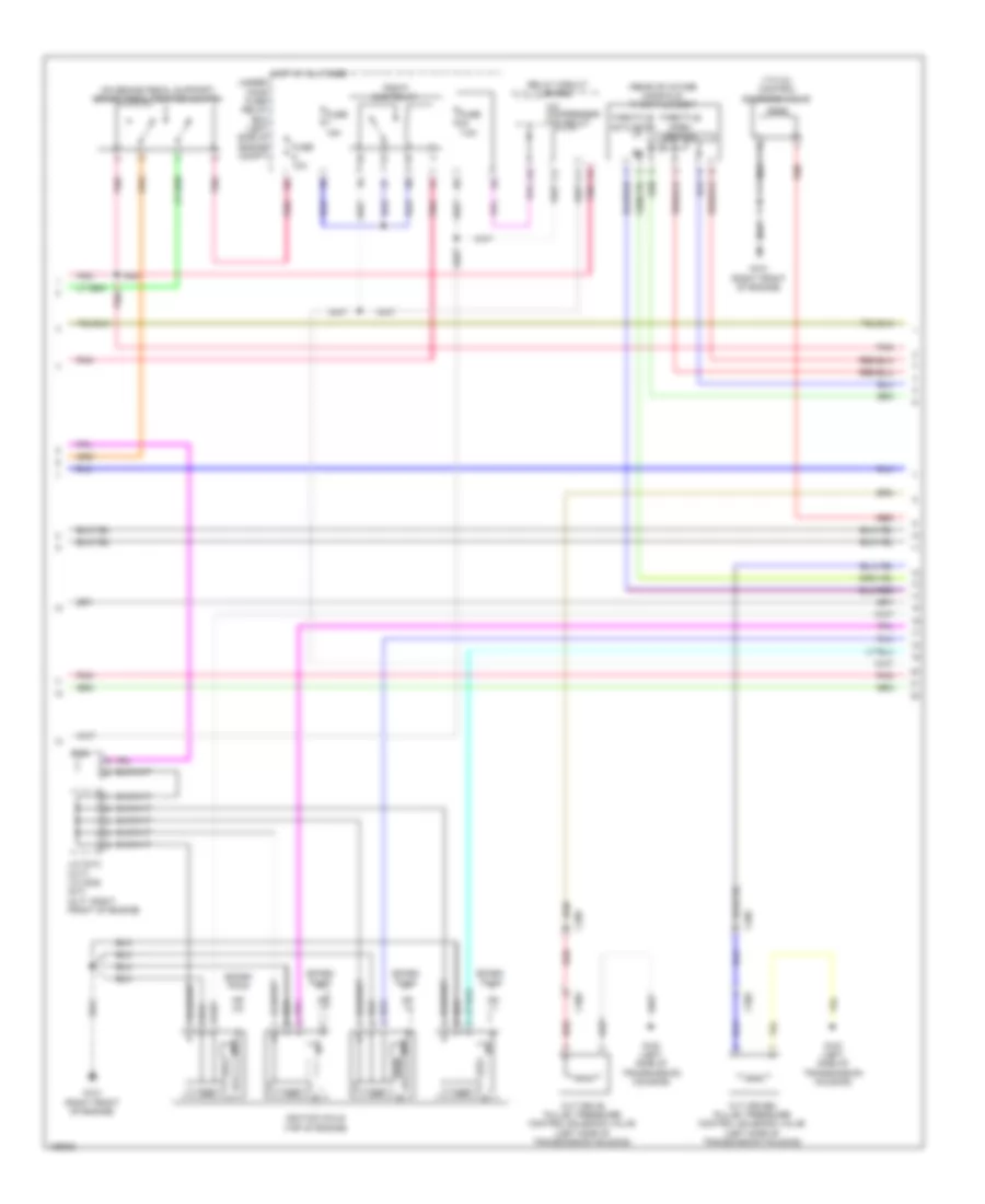
2.0L Hybrid, Engine Controls Wiring Diagram, Except Plug-In Hybrid (5 of 6) for Honda Accord Plug-In 2014
List of elements for 2.0L Hybrid, Engine Controls Wiring Diagram, Except Plug-In Hybrid (5 of 6) for Honda Accord Plug-In 2014:
- (left rear of engine) g101
- (top of engine)
- (top rear of engine) j/c c005
- C203
- Exterior lights system
- Fuse 15a
- Fwd
- Fwd2
- G101 (left rear of engine)
- Gnd
- Hot at all times
- Icm
- Ignition coil 1
- Ignition coil 2
- Ignition coil 3
- Ignition coil 4
- Ignition coil relay
- Pnk
- Red
- Rvs
- Rvs2
- Spark plug
- Transmission range switch (top of transmission)
- Under- hood fuse/relay box (left rear of engine compt)
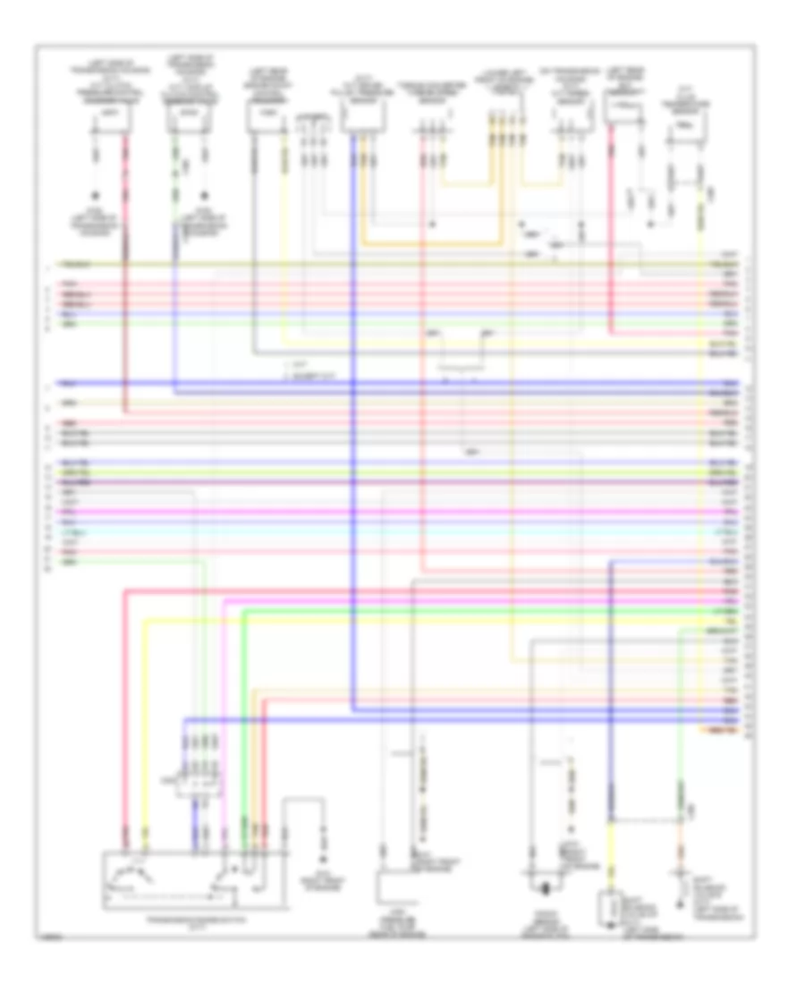
2.0L Hybrid, Engine Controls Wiring Diagram, Except Plug-In Hybrid (6 of 6) for Honda Accord Plug-In 2014
List of elements for 2.0L Hybrid, Engine Controls Wiring Diagram, Except Plug-In Hybrid (6 of 6) for Honda Accord Plug-In 2014:
- (lower left front of engine) electric engine coolant pump
- (rear of intake manifold) throttle body
- (right rear of cylinder head)
- (top left side of cylinder head) injectors
- (top rear of engine) j/c c005
- C10
- C11
- C12
- C13
- C14
- C15
- C16
- C17
- C18
- C19
- C20
- C21
- C22
- C23
- C24
- C25
- C26
- C27
- C28
- C29
- C30
- C31
- C32
- C33
- C34
- C35
- C36
- C37
- C38
- C39
- C40
- C41
- C42
- C43
- C44
- C45
- C46
- C47
- C48
- C49
- C50
- Ckp sensor (lower right rear of engine)
- Cmp
- Cmp sensor b (left rear of cylinder head)
- Computer data lines system
- G101 (left rear of engine)
- G102 (lower left front of engine)
- Knock sensor (rear of engine)
- Map sensor (front of intake manifold)
- Pcm (left front of engine compt)
- Pnk
- Red
- Rocker arm oil control solenoid (front of cylinder bank)
- Rocker arm oil pressure sensor switch (front of cylinder bank)
- Sensor a
- Tan
- Throttle actuator
- Throttle open sensor
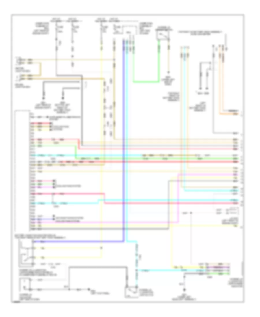
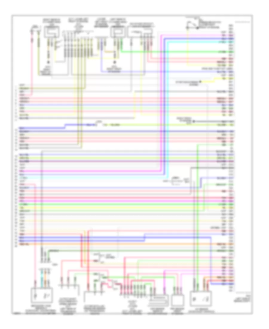
2.0L Hybrid, Engine Controls Wiring Diagram, Plug-In Hybrid (1 of 6) for Honda Accord Plug-In 2014
List of elements for 2.0L Hybrid, Engine Controls Wiring Diagram, Plug-In Hybrid (1 of 6) for Honda Accord Plug-In 2014:
- A10
- A11
- A12
- A13
- A14
- A15
- A16
- A17
- A18
- A19
- A20
- A21
- A22
- A23
- A24
- A25
- A26
- A27
- A28
- A29
- A30
- A31
- A32
- A33
- A34
- A35
- A36
- A37
- A38
- A39
- A40
- A41
- A42
- A43
- A44
- A45
- A46
- A47
- A48
- A49
- A50
- A51
- Anti-lock brakes system
- App sensor (on accelerator pedal support)
- App sensor a
- App sensor b
- C113
- C131
- C203
- Computer data lines system
- Cooling fans system
- Door locks system
- Ect sensor 2 (on radiator lower left outlet)
- Ftp sensor
- Fuel vapor containment valve
- Fuse 10a
- Fuse 15a
- Fuse 2-3 20a
- Fuse 20a
- Fuse 7.5a
- G101 (left rear of engine)
- Hot at all times
- Hot w/ rfc relay energized
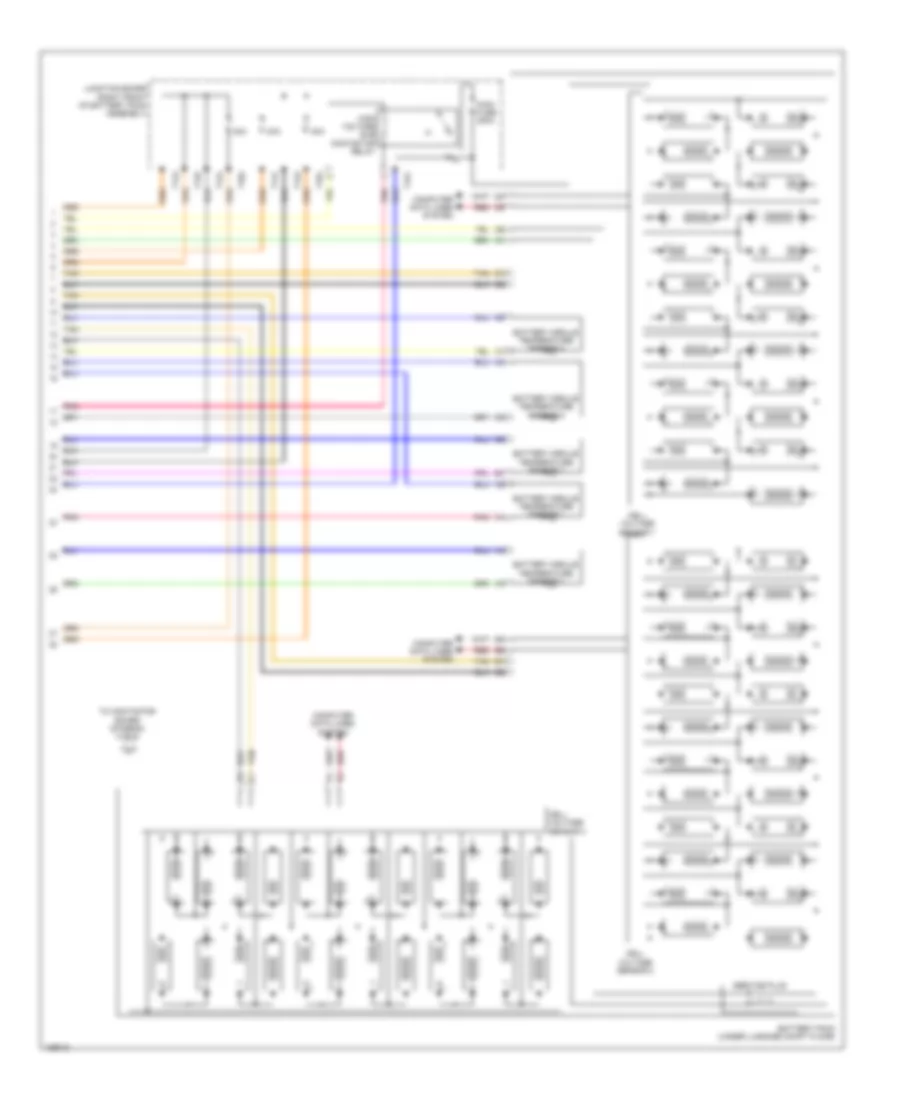
- Navigation & sound systems
- Pcm (left front of engine compt)
- Pgm-fi main relay 1
- Pgm-fi sub relay
- Pnk
- Red
- Shift interlock system
- Shift solenoid valve a (left side of transmission)
- Shift solenoid valve b (left side of transmission)
- Under- hood fuse/ relay box (left rear of engine compt)
2.0L Hybrid, Engine Controls Wiring Diagram, Plug-In Hybrid (2 of 6) for Honda Accord Plug-In 2014
List of elements for 2.0L Hybrid, Engine Controls Wiring Diagram, Plug-In Hybrid (2 of 6) for Honda Accord Plug-In 2014:
- (left front of engine compt) j/c c007
- (lower right front of engine compt) a/c pressure sensor
- (top of fuel tank) fuel tank unit
- (upper left end of dash)
- A17
- A19
- A20
- B12
- C131
- C132
- C201
- C203
- C207
- Computer data lines system
- Dc-dc converter
- Etcs control relay
- F-can h
- F-can l
- F-can transceiver
- Fuel fill door opener solenoid
- Fuel fill door opener solenoid relay
- G502
- G602 (left front of luggage compt)
- G603 (left rear of luggage compt)
- Gauge control module
- Indicator drive circuit
- Instrument cluster system
- Malfunction indicator lamp (mil)
- Pcu (top of traction/ generator motor assembly)
- Pgm-fi main relay 2
- Pnk
- Red
- Secondary ho2s (sensor 2) (in exhaust, downstream of catalytic converter)
- Stabilize circuit
- Tan
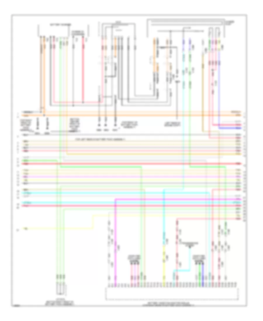
2.0L Hybrid, Engine Controls Wiring Diagram, Plug-In Hybrid (3 of 6) for Honda Accord Plug-In 2014
List of elements for 2.0L Hybrid, Engine Controls Wiring Diagram, Plug-In Hybrid (3 of 6) for Honda Accord Plug-In 2014:
- (left front of engine) evap canister purge valve
- (on brake pedal support) brake pedal position switch
- A/f sensor (on exhaust manifold)
- B10
- B11
- B12
- B13
- B14
- B15
- B16
- B17
- B18
- B19
- B20
- B21
- B22
- B23
- B24
- B25
- B26
- B27
- B28
- B29
- B30
- B31
- B32
- B33
- B34
- B35
- B36
- B37
- B38
- B39
- B40
- B41
- B42
- B43
- B44
- B45
- B46
- B47
- B48
- B49
- B50
- B51
- C131
- C201
- C203
- Computer data lines system
- Cooling fans system
- Door locks system
- E11
- E17
- E23
- Evap leak detection module
- F11
- Fuel fill door opener sensor
- Fuse 10a
- Fuse 15a
- Fuse 18-1 10a
- Fuse 20a
- G101 (left rear of engine)
- G603 (left rear of luggage compt)
- Hot at all times
- Hot w/ ig1a relay energized
- Hot w/ ig1b relay energized
- M10
- M11
- M12
- Micu
- Pcm (left front of engine compt)
- Pnk
- R10
- R11
- Red
- Tan
- Under-dash fuse/relay box (left end of dash)
2.0L Hybrid, Engine Controls Wiring Diagram, Plug-In Hybrid (4 of 6) for Honda Accord Plug-In 2014
List of elements for 2.0L Hybrid, Engine Controls Wiring Diagram, Plug-In Hybrid (4 of 6) for Honda Accord Plug-In 2014:
- (egr valve: left side of engine) (egr valve position sensor: on egr valve assembly) egr valve & egr valve position sensor
- (lower right front of engine) electrical vtc motor
- (lower right front of engine) engine oil pressure sensor
- (top rear of engine) j/c c006
- A13
- Battery condition monitor module (top right rear of battery pack assembly)
- C10
- C104
- C130
- C132
- C201
- C202
- C203
- C30
- C403
- Circuit board
- Computer data lines system
- Ect sensor 1 (left rear of engine)
- Electrical vtc relay circuit
- Engine ewp relay circuit
- Fuel fill door opener switch
- G101 (left rear of engine)
- Inta sensor (top front of cylinder head)
- Maf/iat sensor (on intake air duct)
- Pnk
- Red
- Tan
- Transmission fluid pressure switch a (left side of transmission)
- Transmission fluid pressure switch b (left side of transmission)
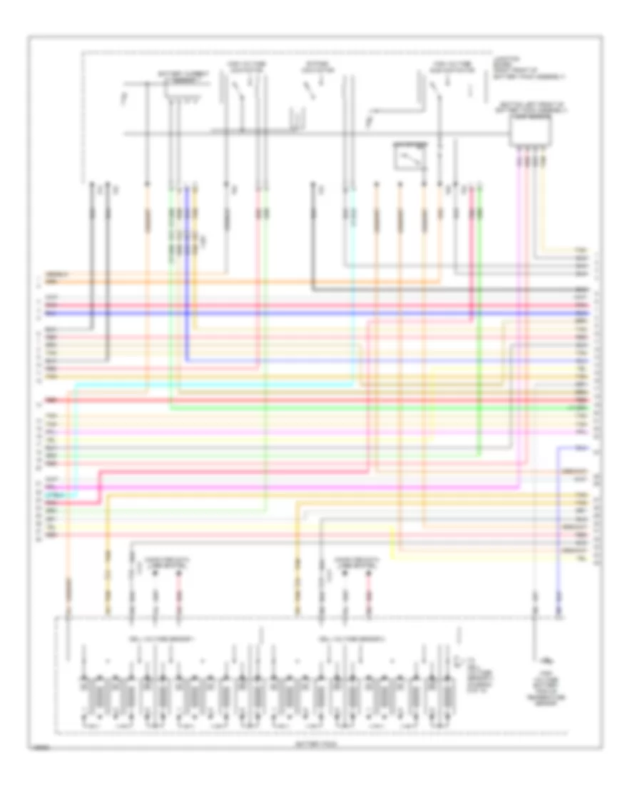
2.0L Hybrid, Engine Controls Wiring Diagram, Plug-In Hybrid (5 of 6) for Honda Accord Plug-In 2014
List of elements for 2.0L Hybrid, Engine Controls Wiring Diagram, Plug-In Hybrid (5 of 6) for Honda Accord Plug-In 2014:
- (left rear of engine) g101
- (top of engine) ignition coil 1
- (top of engine) ignition coil 2
- (top of engine) ignition coil 3
- (top of engine) ignition coil 4
- (top rear of engine) j/c c006
- C203
- Exterior lights system
- Fuse 15a
- Fwd
- Fwd2
- G101 (left rear of engine)
- Gnd
- Hot at all times
- Icm
- Ignition coil relay
- Pnk
- Red
- Rvs
- Rvs2
- Spark plug
- Transmission range switch (top of transmission)
- Under- hood fuse/relay box (left end of dash)
2.0L Hybrid, Engine Controls Wiring Diagram, Plug-In Hybrid (6 of 6) for Honda Accord Plug-In 2014
List of elements for 2.0L Hybrid, Engine Controls Wiring Diagram, Plug-In Hybrid (6 of 6) for Honda Accord Plug-In 2014:
- (left rear of engine)
- (rear of intake manifold) throttle body
- (top left side of cylinder head) injectors
- (top rear of engine) j/c c006
- C10
- C11
- C12
- C13
- C14
- C15
- C16
- C17
- C18
- C19
- C20
- C201
- C21
- C22
- C23
- C24
- C25
- C26
- C27
- C28
- C29
- C30
- C31
- C32
- C33
- C34
- C35
- C36
- C37
- C38
- C39
- C40
- C41
- C42
- C43
- C44
- C45
- C46
- C47
- C48
- C49
- C50
- C51
- Ckp sensor (lower right rear of engine)
- Cmp sensor a (right rear of cylinder head)
- Cmp sensor b (left rear of cylinder head)
- Computer data lines system
- Electric engine coolant pump
- G101
- G101 (left rear of engine)
- G102 (lower left front of engine)
- Knock sensor (rear of engine)
- Map sensor (front of intake manifold)
- Pcm (left front of engine compt)
- Pnk
- Red
- Rocker arm oil control solenoid (front of cylinder head)
- Rocker arm oil pressure sensor (front of cylinder head)
- Tan
- Throttle actuator
- Throttle open sensor
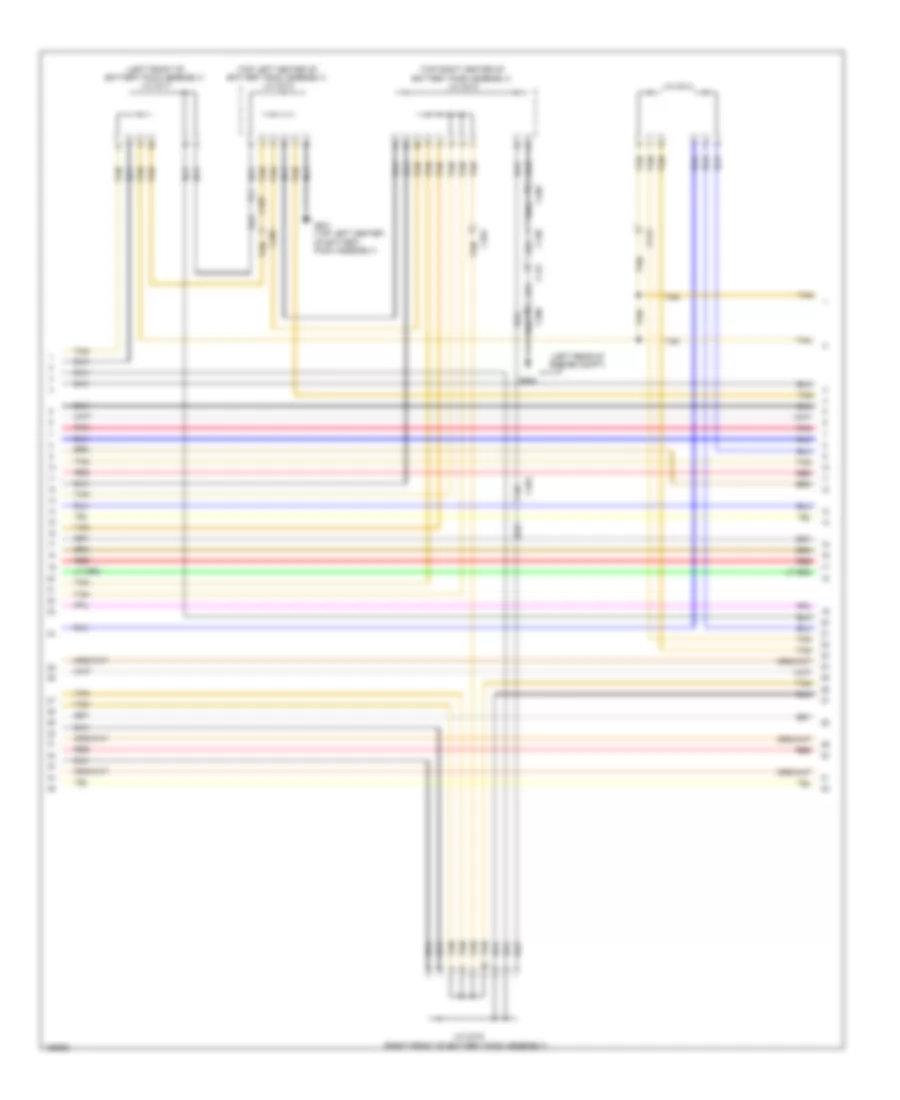
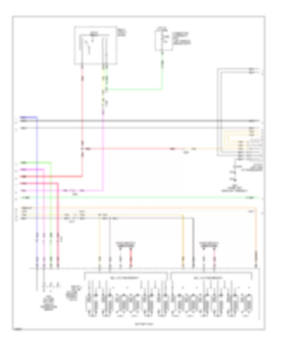
2.0L Hybrid, Hybrid System Wiring Diagram, Except Plug-In Hybrid (1 of 6) for Honda Accord Plug-In 2014
List of elements for 2.0L Hybrid, Hybrid System Wiring Diagram, Except Plug-In Hybrid (1 of 6) for Honda Accord Plug-In 2014:
- A10
- A11
- A12
- A13
- A14
- A15
- A16
- A17
- A18
- A19
- A20
- A21
- A22
- A23
- A24
- A25
- A26
- A27
- A28
- A29
- A30
- A31
- A32
- A33
- A34
- A35
- A36
- Battery condition monitor module (top left rear of battery pack assembly)
- Battery fan relay
- C10
- C104
- C11
- C111
- C12
- C126
- C127
- C129
- C13
- C14
- C15
- C16
- C17
- C18
- C19
- C20
- C21
- C22
- C23
- C24
- C25
- C26
- C27
- C28
- C29
- C30
- C31
- C32
- C33
- C34
- C35
- C36
- C37
- C38
- C39
- C40
- Center junction box
- Computer data lines system
- Driver's junction box
- Fuse 10a
- G652 (under front passenger's seat)
- High voltage battery module fan (front of battery pack assembly)
- Hot at all times
- Hot w/ ig1b relay energized
- Ighld 2 relay
- Leak sensor (top left side of battery pack assembly)
- M11
- Pnk
- Red
- Tan
- Under-dash fuse/relay box (left end of dash)
- Under-dash sub fuse box (left end of dash)
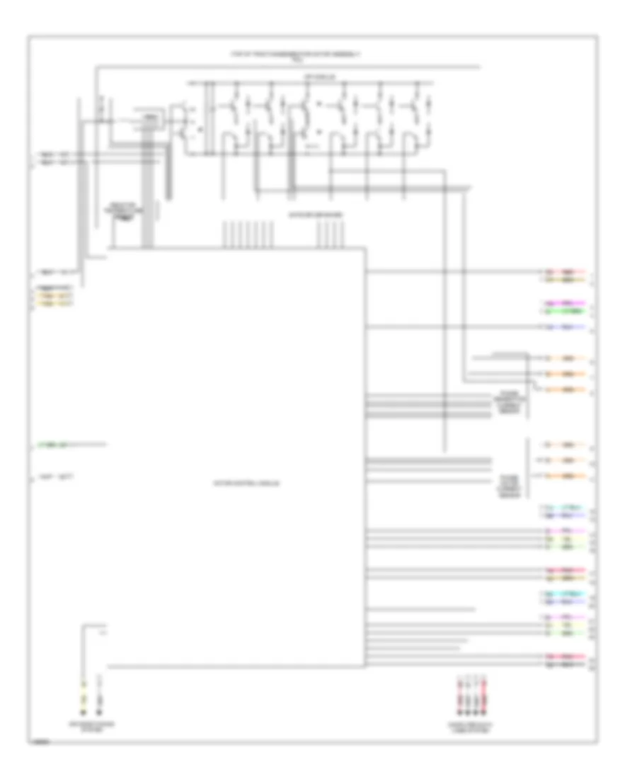
2.0L Hybrid, Hybrid System Wiring Diagram, Except Plug-In Hybrid (2 of 6) for Honda Accord Plug-In 2014
List of elements for 2.0L Hybrid, Hybrid System Wiring Diagram, Except Plug-In Hybrid (2 of 6) for Honda Accord Plug-In 2014:
- (behind left side of front bumper) g301
- (left side of traction/ generator motor assembly) j/c c004
- Air conditioning system
- B10
- C205
- Computer data lines system
- E23
- Fuse 10a
- Gate driver board
- Generator phase current sensor
- Hot at all times
- Ighld1 relay circuit
- Ipin
- Motor control module
- Motor phase current sensor
- Mpi module
- Pcu (top of traction/generator motor assembly)
- Pnk
- Power distribution system
- Reactor temperature sensor
- Red
- Relay circuit board
- T10
- Tan
- Under-dash fuse/relay box (left end of dash)
- Under-hood fuse/relay box (left rear of engine compt)
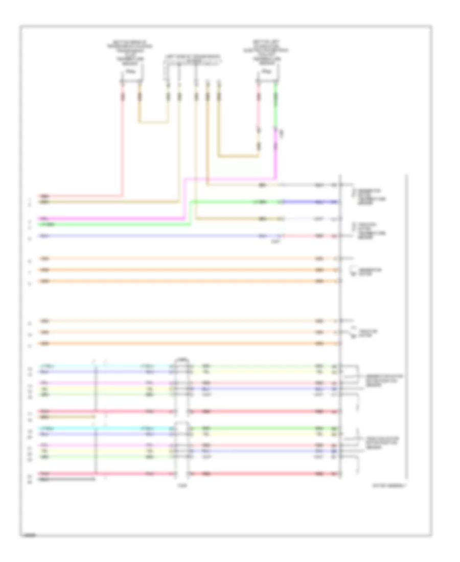
2.0L Hybrid, Hybrid System Wiring Diagram, Except Plug-In Hybrid (3 of 6) for Honda Accord Plug-In 2014
List of elements for 2.0L Hybrid, Hybrid System Wiring Diagram, Except Plug-In Hybrid (3 of 6) for Honda Accord Plug-In 2014:
- (left front of engine compt) j/c c012
- (left side of traction/ generator motor assembly) j/c c004
- C205
- C207
- C401
- C402
- C403
- Electric powertrain coolant temperature sensor (bottom left of radiator)
- Fuse 10a
- Fuse 15a
- Generator motor
- Generator motor rotor position sensor
- Generator motor temperature sensor
- Hot at all times
- Motor assembly
- Pnk
- Red
- Tan
- Traction motor
- Traction motor rotor position sensor
- Traction motor temperature sensor
- Transmission fluid temperature sensor (bottom rear of transmission housing)
- Under-hood fuse/relay box (left rear of engine compt)
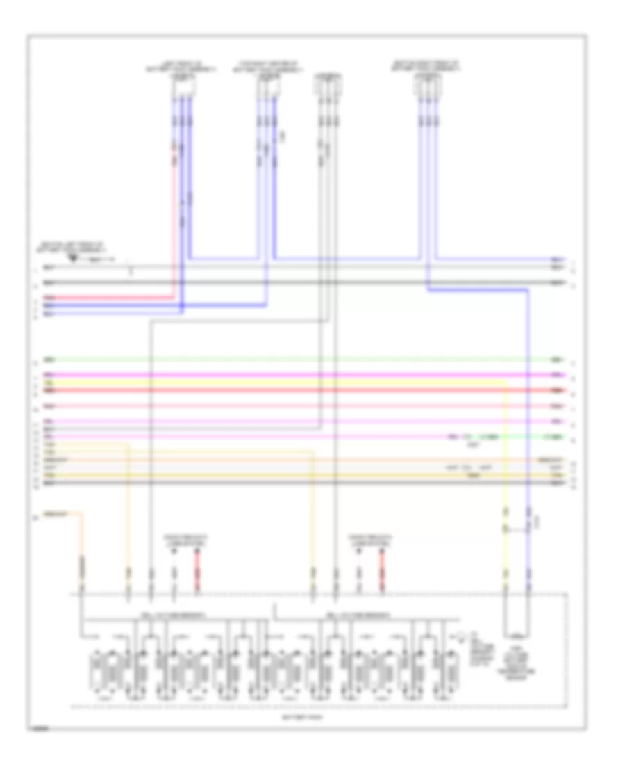
2.0L Hybrid, Hybrid System Wiring Diagram, Except Plug-In Hybrid (4 of 6) for Honda Accord Plug-In 2014
List of elements for 2.0L Hybrid, Hybrid System Wiring Diagram, Except Plug-In Hybrid (4 of 6) for Honda Accord Plug-In 2014:
- (diagram 6 of 6)
- (left front of battery pack assembly) contactor board
- B10
- B11
- B12
- B13
- B14
- B15
- B16
- B17
- B18
- B19
- B20
- B21
- B22
- B23
- B24
- B25
- B26
- B27
- B28
- B29
- B30
- B31
- B32
- Battery condition monitor module (top left rear of battery pack assembly)
- Battery current sensor
- Bypass contactor relay
- C203
- C207
- Computer data lines system
- From battery pack a
- G101 (left rear of engine)
- G801 (top left side of battery pack assembly)
- High voltage contactor relay
- J/c c003 (top left side of battery pack assembly)
- Pcm (left front of engine compt)
- Pnk
- Red
- T131
- T152
- Tan
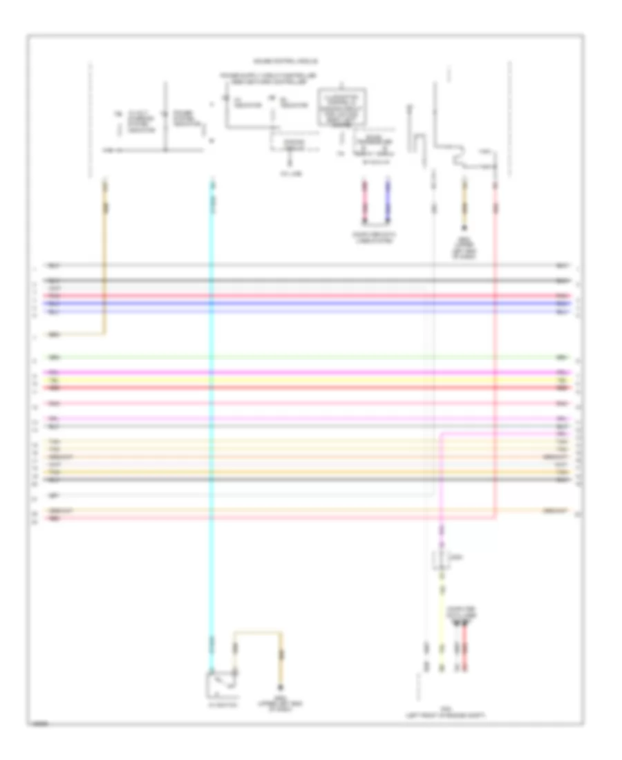
2.0L Hybrid, Hybrid System Wiring Diagram, Except Plug-In Hybrid (5 of 6) for Honda Accord Plug-In 2014
List of elements for 2.0L Hybrid, Hybrid System Wiring Diagram, Except Plug-In Hybrid (5 of 6) for Honda Accord Plug-In 2014:
- (left rear of battery pack assembly) j/c c001
- (left rear of battery pack assembly) j/c c002
- (left rear of engine compt) g351
- (top right front of battery pack assembly) g655
- (top right of battery pack assembly) dc-dc converter
- 12 volt charging system indicator
- A/c compressor (left front of engine)
- A17
- A19
- A20
- C111
- C129
- C404
- C405
- Computer data lines system
- Dimming circuit
- Ev indicator
- Ev switch
- F- can h
- F- can l
- F-can transceiver
- Fuse 150a
- Fuse 15a
- G502 (upper left end of dash)
- Gauge control module
- Hot at all times
- Hot w/ ig1a relay energized
- Indicator drive circuit
- Pnk
- Power system indicator
- Red
- T101
- T122
- T141
- T142
- Tan
- Under-dash fuse/relay box (left end of dash)
- Under-hood fuse/relay box (left rear of engine compt)
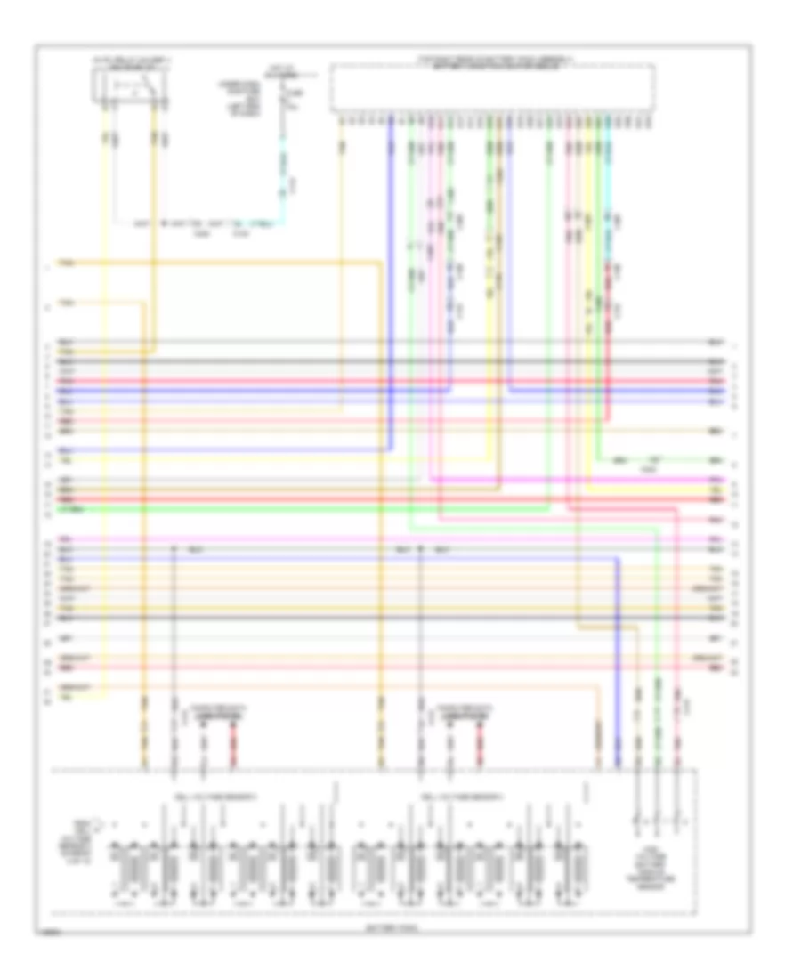
2.0L Hybrid, Hybrid System Wiring Diagram, Except Plug-In Hybrid (6 of 6) for Honda Accord Plug-In 2014
List of elements for 2.0L Hybrid, Hybrid System Wiring Diagram, Except Plug-In Hybrid (6 of 6) for Honda Accord Plug-In 2014:
- 30a
- Battery module temperature sensor 1
- Battery module temperature sensor 2
- Battery module temperature sensor 3
- Battery module temperature sensor 4
- Battery module temperature sensor 5
- Battery pack (under luggage compt floor)
- Cell voltage sensor 1
- Cell voltage sensor 2
- Cell voltage sensor 3
- Computer data lines system
- High voltage sub contactor relay
- Junction board (right front of battery pack assembly)
- Main fuse 200a
- Pnk
- Red
- Service plug
- T123
- T124
- T132
- T143
- T144
- T151
- T181
- T182
- Tan
- To contactor board (diagram 4 of 6)
2.0L Hybrid, Hybrid System Wiring Diagram, Plug-In Hybrid (1 of 10) for Honda Accord Plug-In 2014
List of elements for 2.0L Hybrid, Hybrid System Wiring Diagram, Plug-In Hybrid (1 of 10) for Honda Accord Plug-In 2014:
- (left front of battery pack assembly)
- (top right front of battery pack assembly)
- (top right of battery pack assembly) dc-dc converter
- A10
- A11
- A12
- A13
- A14
- A15
- A16
- A17
- A18
- A19
- A20
- A21
- A22
- A23
- A24
- A25
- A26
- A27
- A28
- A29
- A30
- A31
- A32
- A33
- A34
- A35
- A36
- Air conditioning system
- Battery condition monitor module (top right rear of battery pack assembly)
- C104
- C111
- C119
- C126
- C130
- C131
- C132
- C201
- C206
- C401
- C403
- C404
- C405
- Center junction box
- Charge lid actuator (left end of dash)
- Charge lid illumination lamp switch
- Charge lid illumination lamp/charge indicator
- Charge lid illumination lamp/charge indicator relay (in under-dash fuse/relay box b)
- Charge lid opener switch
- Cooling fans system
- Drive's junction box
- E23
- Fuse 10a
- Fuse 150a
- Fuse 18-1 10a
- G301 (under left headlight assembly)
- G351 (left rear of engine compt)
- G401 (left kick panel)
- G502 (upper left end of dash)
- G655 (bottom left front of battery pack assembly)
- G804
- G805
- Hot at all times
- J/c c007 (left front of engine compt)
- M11
- Micu
- P16
- P20
- P21
- Pnk
- R11
- Red
- T101
- T65
- T66
- T71
- Tan
- Under dash fuse/relay box (left end of dash)
- Under hood fuse/relay box (left rear of engine compt)
2.0L Hybrid, Hybrid System Wiring Diagram, Plug-In Hybrid (2 of 10) for Honda Accord Plug-In 2014
List of elements for 2.0L Hybrid, Hybrid System Wiring Diagram, Plug-In Hybrid (2 of 10) for Honda Accord Plug-In 2014:
- (bottom center front of battery pack assembly)
- (left rear of engine compt)
- (top front of battery pack assembly)
- (top left rear of battery pack assembly)
- (top right front of battery pack assembly)
- Battery charger
- Battery condition monitor module (top right rear of battery pack assembly)
- C10
- C11
- C118
- C12
- C126
- C13
- C130
- C131
- C132
- C14
- C15
- C16
- C17
- C18
- C19
- C20
- C206
- C21
- C22
- C23
- C24
- C25
- C26
- C27
- C28
- C29
- C30
- C31
- C32
- C33
- C34
- C35
- C36
- C37
- C38
- C39
- C40
- C401
- C403
- C405
- C406
- C410
- Charge ac condenser
- Charge inlet
- Computer data lines system
- G532
- G656
- G802
- G803
- G804
- J/c c015 (bottom right front of battery pack assembly)
- Pnk
- Red
- T11
- T12
- T13
- T14
- T61
- T63
- Tan
- Transmissions system
2.0L Hybrid, Hybrid System Wiring Diagram, Plug-In Hybrid (3 of 10) for Honda Accord Plug-In 2014
List of elements for 2.0L Hybrid, Hybrid System Wiring Diagram, Plug-In Hybrid (3 of 10) for Honda Accord Plug-In 2014:
- (bottom left front of battery pack assembly) leak sensor
- Battery current sensor
- Battery pack
- Bypass contactor
- C401
- C411
- Cell voltage sensor 1
- Cell voltage sensor 2
- Computer data lines system
- High voltage battery module temperature sensor
- High voltage contactor
- High voltage sub contactor
- Junction board (right front of battery pack assembly)
- Main switch
- Pnk
- Red
- T51
- T52
- T57
- T62
- T64
- T72
- Tan
- To cell voltage sensor 3 (diagram 5 of 10)
2.0L Hybrid, Hybrid System Wiring Diagram, Plug-In Hybrid (4 of 10) for Honda Accord Plug-In 2014
List of elements for 2.0L Hybrid, Hybrid System Wiring Diagram, Plug-In Hybrid (4 of 10) for Honda Accord Plug-In 2014:
- (left front of battery pack assembly) j/c c017
- (left rear of engine compt)
- (top left center of battery pack assembly) j/c c012
- (top right center of battery pack assembly) j/c c010
- C130
- C131
- C206
- C401
- C403
- C404
- C405
- C413
- G532
- G801 (top left center of battery pack assembly)
- J/c c014
- J/c c016 (right front of battery pack assembly)
- Pnk
- Red
- Tan
2.0L Hybrid, Hybrid System Wiring Diagram, Plug-In Hybrid (5 of 10) for Honda Accord Plug-In 2014
List of elements for 2.0L Hybrid, Hybrid System Wiring Diagram, Plug-In Hybrid (5 of 10) for Honda Accord Plug-In 2014:
- (in ipu relay holder 1) ighldb relay
- (top right rear of battery pack assembly) battery condition monitor module
- B10
- B11
- B12
- B13
- B14
- B15
- B16
- B17
- B18
- B19
- B20
- B21
- B22
- B23
- B24
- B25
- B26
- B27
- B28
- B29
- B30
- B31
- B32
- Battery pack
- C112
- C118
- C126
- C130
- C131
- C401
- C402
- C403
- C405
- C412
- C413
- Cell voltage sensor 3
- Cell voltage sensor 4
- Computer data lines system
- From a cell voltage sensor 2 (diagram 3 of 10)
- Fuse 10a
- High voltage battery module temperature sensor
- Hot at all times
- Pnk
- Red
- Tan
- Under dash sub fuse box (left end of dash)
2.0L Hybrid, Hybrid System Wiring Diagram, Plug-In Hybrid (6 of 10) for Honda Accord Plug-In 2014
List of elements for 2.0L Hybrid, Hybrid System Wiring Diagram, Plug-In Hybrid (6 of 10) for Honda Accord Plug-In 2014:
- 10v line
- 12 volt charging system indicator
- A17
- A30
- A31
- B- can h
- B- can l
- B-can transceiver
- B39
- C203
- Computer data lines system
- Dimming circuit
- Ev indicator
- G502 (upper left end of dash)
- Gauge control module
- Hv indicator
- Hv switch
- Illumination control & dimming circuit for lcd (mid) back light (white)
- Pcm (left front of engine compt)
- Pnk
- Power system indicator
- Red
- Tan
2.0L Hybrid, Hybrid System Wiring Diagram, Plug-In Hybrid (7 of 10) for Honda Accord Plug-In 2014
List of elements for 2.0L Hybrid, Hybrid System Wiring Diagram, Plug-In Hybrid (7 of 10) for Honda Accord Plug-In 2014:
- (bottom left front of battery pack assembly) g655
- (bottom right front of battery pack assembly) j/c c015
- (left front of battery pack assembly) j/c c017
- (top right center of battery pack assembly) j/c c010
- Battery pack
- C130
- C205
- C207
- C401
- C403
- C413
- C414
- Cell voltage sensor 5
- Cell voltage sensor 6
- Computer data lines system
- High voltage battery module temperature sensor
- J/c c014
- Pnk
- Red
- Tan
- To cell voltage sensor 7 (diagram 8 of 10)
2.0L Hybrid, Hybrid System Wiring Diagram, Plug-In Hybrid (8 of 10) for Honda Accord Plug-In 2014
List of elements for 2.0L Hybrid, Hybrid System Wiring Diagram, Plug-In Hybrid (8 of 10) for Honda Accord Plug-In 2014:
- B10
- Battery pack
- C130
- C131
- C205
- C405
- C414
- Cell voltage sensor 7
- Cell voltage sensor 8
- Computer data lines system
- From cell b
- Fuse 10a
- G301 (under left headlight assembly)
- High voltage battery module temperature sensor
- Hot at all times
- Ighld1 relay
- J/c c013 (left side of transmission)
- Pnk
- Red
- Relay circuit board
- Tan
- Under hood fuse/relay box (left rear of engine compt)
- Voltage sensor 6 (diagram 7 of 10)
2.0L Hybrid, Hybrid System Wiring Diagram, Plug-In Hybrid (9 of 10) for Honda Accord Plug-In 2014
List of elements for 2.0L Hybrid, Hybrid System Wiring Diagram, Plug-In Hybrid (9 of 10) for Honda Accord Plug-In 2014:
- (top of traction/generator motor assembly) pcu
- Air conditioning system
- Computer data lines system
- Gate driver board
- Ipin
- Motor control module
- Mpi module
- Phase generator current sensor
- Phase motor current sensor
- Pnk
- Reactor temperature sensor
- Red
- Tan
2.0L Hybrid, Hybrid System Wiring Diagram, Plug-In Hybrid (10 of 10) for Honda Accord Plug-In 2014
List of elements for 2.0L Hybrid, Hybrid System Wiring Diagram, Plug-In Hybrid (10 of 10) for Honda Accord Plug-In 2014:
- (bottom left of radiator) electric powertrain coolant temperature sensor
- (bottom rear of transmission housing) transmission fluid temperature sensor
- (left side of transmission) j/c c013
- C207
- C407
- C408
- C409
- Generator motor
- Generator motor rotor position sensor
- Generator motor temperature sensor
- Motor assembly
- Pnk
- Red
- Traction motor
- Traction motor rotor position sensor
- Traction motor temperature sensor
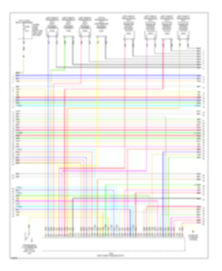
2.4L
2.4L, Engine Performance Wiring Diagram (1 of 5) for Honda Accord Plug-In 2014
List of elements for 2.4L, Engine Performance Wiring Diagram (1 of 5) for Honda Accord Plug-In 2014:
- A/c pressure sensor (lower right front of engine compt)
- A10
- A11
- A12
- A13
- A14
- A15
- A16
- A17
- A18
- A19
- A20
- A21
- A22
- A23
- A24
- A25
- A26
- A27
- A28
- A29
- A30
- A31
- A32
- A33
- A34
- A35
- A36
- A37
- A38
- A39
- A40
- A41
- A42
- A43
- A44
- A45
- A46
- A47
- A48
- A49
- A50
- A51
- Air conditioning system
- B10
- B11
- B12
- B13
- B14
- B15
- B16
- B17
- B18
- B19
- B20
- B21
- C129
- Clutch pedal position switch b (m/t)
- Computer data lines system
- Cooling fans system
- Door locks system
- Electronic power steering system
- Etcs control relay
- Ftp sensor (behind center of fuel tank)
- Fuse 15a
- Fuse 20a
- G101 (right front of engine)
- G102 (left rear of engine)
- G401 (left kick panel)
- Hot at all times
- Ignition coil relay
- Injector relay
- Injectors (top left side of cylinder head)
- J/c c021 (left side of dash)
- Nca
- Pcm (left side of engine compt)
- Pgm-fi main relay 1
- Pnk
- Red
- Rocker arm oil control solenoid (front of cylinder bank)
- Rocker arm oil pressure switch (front of cylinder bank)
- Shift interlock system
- Sound systems
- Starting/ charging system
- Starting/charging system
- Under- hood fuse/ relay box (left side of engine compt)
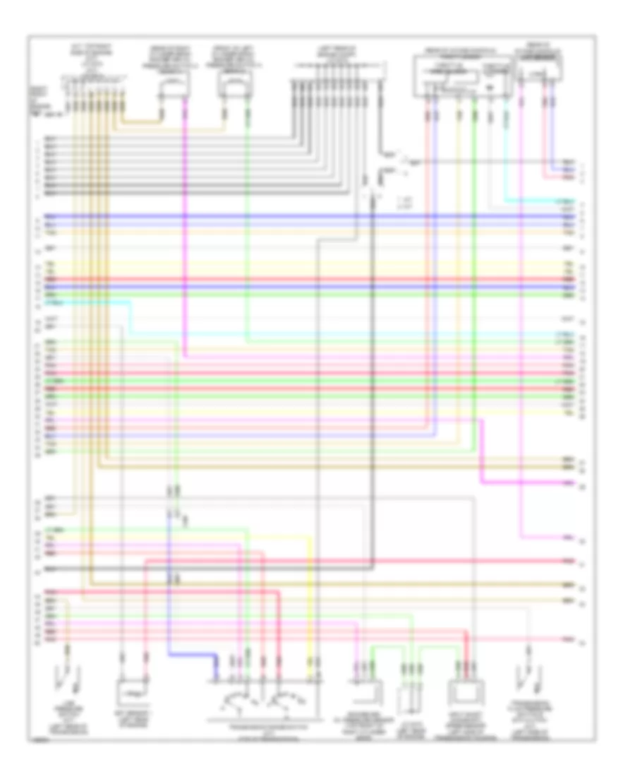
2.4L, Engine Performance Wiring Diagram (2 of 5) for Honda Accord Plug-In 2014
List of elements for 2.4L, Engine Performance Wiring Diagram (2 of 5) for Honda Accord Plug-In 2014:
- (top of fuel tank) fuel tank unit
- (under center rear of vehicle)
- A17
- A19
- A20
- App sensor (on accelerator pedal support)
- C105
- C112
- C204
- Clutch pedal position switch a (coupe m/t)
- Computer data lines system
- Diode b
- Diode c
- Drive circuit
- E10
- E11
- E13
- E16
- E17
- Ect sensor 2 (on radiator lower left outlet)
- Eld
- Evap canister purge valve (right rear of engine)
- Evap canister vent shut valve (under middle rear of vehicle, on evap control canister)
- F-can h
- F-can l
- F-can transceiver
- F11
- F18
- Fuse 10a
- Fuse 125a
- Fuse 15a
- Fuse 20a
- Fuse 7.5a
- G301 (behind left side of front bumper)
- G401 (left kick panel)
- G502 (upper left end of dash)
- G602
- Gauge control module
- Hot at all times
- Hot in on or start
- Ind lamp (mil) malfunction
- Indicator
- Instrument cluster system
- M11
- Main circuit
- Micu
- Pgm-fi main relay
- Pnk
- Red
- Reverse lockout solenoid (m/t) (on transmission housing)
- Reverse relay
- Starting/ charging system
- Under-dash fuse/ relay box (left end of dash)
- Under-hood fuse/ relay box (left side of engine compt)
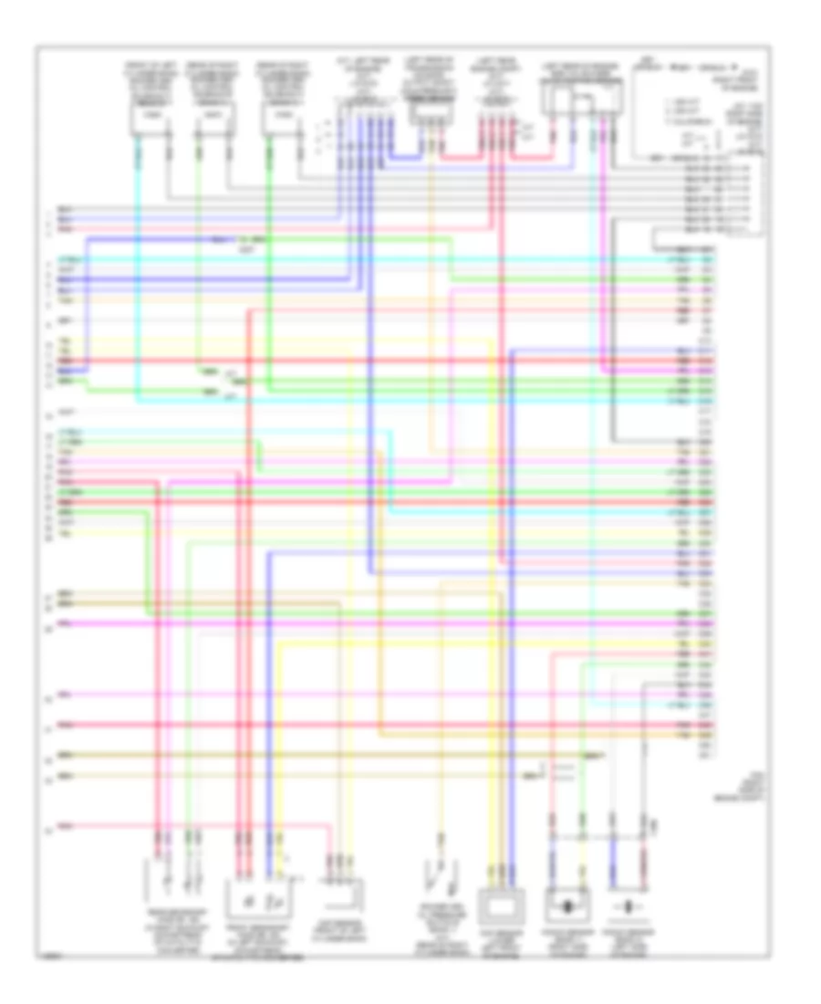
2.4L, Engine Performance Wiring Diagram (3 of 5) for Honda Accord Plug-In 2014
List of elements for 2.4L, Engine Performance Wiring Diagram (3 of 5) for Honda Accord Plug-In 2014:
- (on brake pedal support) brake pedal position switch
- (rear of intake manifold) throttle body
- A/c compressor fan relay
- C204
- C205
- C302
- Cvt drive pulley pressure control solenoid valve (left side of transmission housing)
- Cvt driven pulley pressure control solenoid valve (left side of transmission housing)
- Fuse 10a
- Fuse 15a
- Fuse 7.5a
- G101 (right front of engine)
- G151 (left side of transmission housing)
- Hot at all times
- Icm
- Ignition coils (top of engine)
- J/c c010 (cvt) j/c c008 (m/t) (cvt: right front of engine)
- Pgm-fi sub relay
- Pnk
- Red
- Relay circuit board
- Spark plug
- Throttle actuator
- Throttle open sensor
- Under- hood fuse/ relay box (left side of engine compt)
- Vtc oil control solenoid valve
2.4L, Engine Performance Wiring Diagram (4 of 5) for Honda Accord Plug-In 2014
List of elements for 2.4L, Engine Performance Wiring Diagram (4 of 5) for Honda Accord Plug-In 2014:
- (cvt) cvt driven pulley pressure sensor
- (left rear of engine) ect sensor 1
- (left rear of engine) engine mount control solenoid
- (left side of transmission housing) (cvt) cvt clutch pressure control solenoid valve
- (left side of transmission housing) (cvt) cvt lock-up clutch control solenoid valve
- (lower left front of engine) j/c c011
- (on transmission housing) (cvt) cvt speed sensor
- C204
- C205
- C302
- Cvt
- Cvt fluid temperature sensor
- Except cvt
- G101 (right front of engine)
- G152 (left side of transmission housing)
- High pressure fuel pump (rear of engine)
- J/c c009
- Knock sensor (left side of engine block)
- Pnk
- Red
- Shift solenoid valve b (cvt) (left side of transmission)
- Shift solenoid valve o/p (cvt) (left side of transmission)
- Tan
- Torque converter turbine speed sensor
- Transmission range switch (cvt)
2.4L, Engine Performance Wiring Diagram (5 of 5) for Honda Accord Plug-In 2014
List of elements for 2.4L, Engine Performance Wiring Diagram (5 of 5) for Honda Accord Plug-In 2014:
- (cvt: lower left front of engine) (m/t) j/c c009 (cvt) j/c c011
- (left rear of cylinder head) cmp sensor b
- (lower left front of engine) ckp sensor
- (on intake air duct) maf/iat sensor
- (or red)
- (pins: b35 to b37 not used)
- (right front of engine) g101
- (right rear of cylinder head) cmp sensor a
- A/f sensor (on exhaust manifold)
- B22
- B23
- B24
- B25
- B26
- B27
- B28
- B29
- B30
- B31
- B32
- B33
- B34
- B38
- B39
- B40
- B41
- B42
- B43
- B44
- B45
- B46
- B47
- B48
- B49
- B50
- B51
- C10
- C11
- C12
- C13
- C14
- C15
- C16
- C17
- C18
- C19
- C20
- C204
- C21
- C22
- C23
- C24
- C25
- C26
- C27
- C28
- C29
- C30
- C31
- C32
- C33
- C34
- C35
- C36
- C37
- C38
- C39
- C40
- C41
- C42
- C43
- C44
- C45
- C46
- C47
- C48
- C49
- C50
- C51
- Cvt
- Cvt drive pulley pressure sensor (on transmission housing)
- Frp sensor (front of engine)
- G101 (right front of engine)
- J/c c011 (cvt) j/c c009 (m/t) (cvt: lower left front of engine)
- M/t
- M/t pnk
- Map sensor (rear of intake manifold)
- Oil pressure switch (lower right front of engine)
- Output shaft (countershaft) speed sensor (m/t) (left rear of transmission housing)
- Pcm (left side of engine compt)
- Pnk
- Red
- Secondary ho2s (sensor 2) (in exhaust, downstream of catalytic converter)
- Starting/charging
- System
- Tan
3.5L
3.5L, Engine Performance Wiring Diagram (1 of 7) for Honda Accord Plug-In 2014
List of elements for 3.5L, Engine Performance Wiring Diagram (1 of 7) for Honda Accord Plug-In 2014:
- (left side of dash)
- (right side of engine compt) pcm
- A/c pressure sensor (lower right front of engine compt)
- A/t
- A10
- A11
- A12
- A13
- A14
- A15
- A16
- A17
- A18
- A19
- A20
- A21
- A22
- A23
- A24
- A25
- A26
- A27
- A28
- A29
- A30
- A31
- A32
- A33
- A34
- A35
- A36
- A37
- A38
- A39
- A40
- A41
- A42
- A43
- A44
- A45
- A46
- A47
- A48
- A49
- A50
- A51
- Air conditioning system
- App sensor (on accelerator pedal support)
- Brake light relay (left front of engine compt)
- Brake pedal position switch (on brake pedal support)
- C112
- C129
- C18
- C207
- Clutch pedal position switch b (m/t)
- Computer data lines system
- Cooling fans system
- E10
- E11
- E13
- E17
- Ect sensor 2 (on radiator lower left outlet)
- Eld
- Electronic power steering system
- Etcs control relay
- F18
- Ftp sensor (behind center of fuel tank)
- Fuse 10a
- Fuse 125a
- Fuse 15 15a
- Fuse 18 15a
- Fuse 20a
- G301 (behind left side of front bumper)
- Hot at all times
- Hot w/ ig1a relay energized
- J/c c021 (left side of dash)
- Keyless access control unit
- M/t
- Maf/iat sensor (on intake air duct)
- Micu
- Pgm-fi main relay 1
- Pgm-fi main relay 2
- Pnk
- Red
- Sensor a
- Sensor b
- Shift interlock system
- Sound systems
- Starting/ charging system
- Starting/charging system
- Tan
- Under- dash fuse/ relay box (left end of dash)
- Under-hood fuse/relay box (left side of engine compt)
3.5L, Engine Performance Wiring Diagram (2 of 7) for Honda Accord Plug-In 2014
List of elements for 3.5L, Engine Performance Wiring Diagram (2 of 7) for Honda Accord Plug-In 2014:
- (a/t) active control engine mount (acm) control relay
- (left end of dash) (a/t) engine mount control unit
- (left rear engine compt) j/c c017
- (left rear of engine compt) j/c c012
- (lower middle rear of engine compt) rear engine mount actuator
- (right rear of engine) engine mount control solenoid
- A/t
- C112
- C129
- C201
- C202
- C207
- Clutch pedal position switch a
- Computer data lines system
- Evap canister purge valve (right rear of engine)
- Front engine mount actuator (lower middle front of engine compt)
- Fuel pump control module (left "c" pillar)
- Fuel tank unit (top of fuel tank)
- G401 (left kick panel)
- G602 (under center rear of vehicle)
- Injector 6 (under intake manifold, in left cylinder bank)
- Injectors 1, 2 & 3 (under intake manifold, in right cylinder bank)
- Injectors 4 & 5 (under intake manifold, in left cylinder bank)
- Instrument cluster system
- J/c c014 (a/t) j/c c016 (m/t) (a/t: right front of engine)
- M/t
- Pnk
- Red
- Reverse lockout solenoid (m/t) (on transmission housing)
- Tan
3.5L, Engine Performance Wiring Diagram (3 of 7) for Honda Accord Plug-In 2014
List of elements for 3.5L, Engine Performance Wiring Diagram (3 of 7) for Honda Accord Plug-In 2014:
- (a/t: right front of engine) (m/t) j/c c016 (a/t) j/c c014
- (under middle rear of vehicle, on evap control canister)
- A/t
- Atf temperature sensor (a/t) (on transmission)
- C105
- C112
- C207
- Evap canister vent shut valve
- Exterior lights system
- F11
- Fan relay radiator
- Fuse 15a
- Fuse 20a
- Fuse 7.5a
- Fuse 9 15a
- Hot at all times
- Hot w/ ig1a relay energized
- Ignition coil relay
- J/c c012 (a/t) j/c c019 (m/t) (a/t: left rear of engine compt)
- J/c c014 (a/t) j/c c016 (m/t) (a/t: right front of engine)
- M/t
- Pgm-fi sub relay
- Pnk
- Red
- Relay circuit board
- Tan
- Transmission fluid pressure switch b (3rd clutch) (a/t) (left side of transmission)
- Transmission fluid pressure switch c (4th clutch) (a/t) (left side of transmission)
- Transmission fluid pressure switch d (5th clutch) (a/t)
- Under- dash fuse/ relay box (left end of dash)
- Under- dash sub fuse box (left end of dash)
- Under-hood fuse/relay box (left side of engine compt)
3.5L, Engine Performance Wiring Diagram (4 of 7) for Honda Accord Plug-In 2014
List of elements for 3.5L, Engine Performance Wiring Diagram (4 of 7) for Honda Accord Plug-In 2014:
- (in left exhaust manifold) front a/f sensor (b2, s1)
- (in right exhaust manifold) rear a/f sensor (b1, s1)
- A/t
- A17
- A19
- A20
- California
- Computer data lines system
- Drive circuit
- Except california
- F-can h
- F-can l
- F-can transceiver
- G101 (right front of engine)
- G502 (upper left end of dash)
- Gauge control module
- Icm
- Ignition coils (1, 2 & 3: top of right cylinder bank) (4, 5 & 6: top of left cylinder bank)
- Ind lamp (mil) malfunction
- Indicator
- J/c c015 (a/t) j/c c019 (m/t) (a/t: left rear of engine)
- M/t
- Main circuit
- Pnk
- Red
- Spark plug
- Tan
3.5L, Engine Performance Wiring Diagram (5 of 7) for Honda Accord Plug-In 2014
List of elements for 3.5L, Engine Performance Wiring Diagram (5 of 7) for Honda Accord Plug-In 2014:
- (left side of transmission) (a/t) a/t clutch pressure control solenoid valve a
- (left side of transmission) (a/t) a/t clutch pressure control solenoid valve b
- (left side of transmission) (a/t) a/t clutch pressure control solenoid valve c
- (left side of transmission) (a/t) a/t clutch pressure control solenoid valve d
- (left side of transmission) (a/t) shift solenoid valve a
- (left side of transmission) (a/t) shift solenoid valve b
- (left side of transmission) (a/t) shift solenoid valve c
- (top of transmission) (a/t) line pressure solenoid valve a
- B10
- B11
- B12
- B13
- B14
- B15
- B16
- B17
- B18
- B19
- B20
- B21
- B22
- B23
- B24
- B25
- B26
- B27
- B28
- B29
- B30
- B31
- B32
- B33
- B34
- B35
- B36
- B37
- B38
- B39
- B40
- B41
- B42
- B43
- B44
- B45
- B46
- B47
- B48
- B49
- B50
- B51
- Fuse 7.5a
- Hot w/ ig1b relay energized
- M11
- Pcm (right side of engine compt)
- Pnk
- Red
- Starting/ charging system
- Tan
- Transmission fluid pressure switch a (2nd clutch) (a/t)
- Under- dash fuse/ relay box (left end of dash)
3.5L, Engine Performance Wiring Diagram (6 of 7) for Honda Accord Plug-In 2014
List of elements for 3.5L, Engine Performance Wiring Diagram (6 of 7) for Honda Accord Plug-In 2014:
- (a/t: top right side of engine) (m/t) j/c c018 (a/t) j/c c013
- (front of left cylinder bank) rocker arm oil pressure switch a (bank 2)
- (left rear of engine compt) j/c c012
- (rear of intake manifold) map sensor
- (rear of intake manifold) throttle body
- (rear of right cylinder bank) rocker arm oil pressure switch a (bank 1)
- (right front of engine) g101
- A/t
- C207
- Ect sensor 1 (left rear of engine)
- Input shaft (mainshaft) speed sensor (left side of transmission housing)
- J/c c015 (left rear of engine)
- Line pressure switch (a/t) (left rear of transmission)
- M/t
- Pnk
- Red
- Rocker arm oil pressure sensor (top front of right cylinder bank)
- Tan
- Throttle actuator
- Throttle open sensor
- Transmission fluid pressure switch e (6th clutch) (a/t) (left side of transmission)
- Transmission range switch (a/t) (top of transmission)
3.5L, Engine Performance Wiring Diagram (7 of 7) for Honda Accord Plug-In 2014
List of elements for 3.5L, Engine Performance Wiring Diagram (7 of 7) for Honda Accord Plug-In 2014:
- (a/t: left rear of engine) (m/t) j/c c019 (a/t) j/c c015
- (a/t: top right side of engine) (m/t) j/c c018 (a/t) j/c c013
- (front of left cylinder bank) rocker arm oil control solenoid a (bank 2)
- (left rear engine compt) (m/t) j/c c017 (a/t) j/c c015
- (left rear of engine) egr valve & egr valve position sensor
- (left rear of transmission housing) output shaft (countershaft) speed sensor
- (rear of right cylinder bank) rocker arm oil control solenoid a (bank 1)
- (rear of right cylinder bank) rocker arm oil control solenoid b (bank 1)
- A/t
- C10
- C11
- C12
- C13
- C14
- C15
- C16
- C17
- C18
- C19
- C20
- C206
- C207
- C21
- C22
- C23
- C24
- C25
- C26
- C27
- C28
- C29
- C30
- C31
- C32
- C33
- C34
- C35
- C36
- C37
- C38
- C39
- C40
- C41
- C42
- C43
- C44
- C45
- C46
- C47
- C48
- C49
- C50
- C51
- California
- Ckp sensor (lower left front of engine)
- Cmp sensor (front of left cylinder bank)
- Front secondary ho2s (b2, s2) (in left exhaust, downstream of catalytic converter)
- G101 (right front of engine)
- Knock sensor (bank 1) (right side of engine)
- Knock sensor (bank 2) (left side of engine)
- M/t
- Pcm (right side of engine compt)
- Pnk
- Rear secondary ho2s (b1, s2) (in right exhaust, downstream of catalytic converter)
- Red
- Rocker arm oil pressure switch b (bank 1) (a/t) (rear of right cylinder bank)
- Tan
- Usa a/t
- Usa m/t