ENGINE PERFORMANCE
2.4L
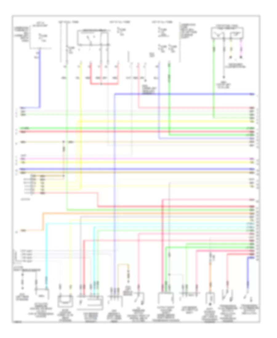
2.4L, Engine Performance Wiring Diagram (1 of 5) for Honda CR-V EX-L 2014

List of elements for 2.4L, Engine Performance Wiring Diagram (1 of 5) for Honda CR-V EX-L 2014:
- (bottom left rear of radiator) ect sensor 2
- (near fuel tank) evap canister vent shut valve
- (right front front of engine compt) a/c pressure sensor
- A/c condenser fan relay
- A10
- A11
- A12
- A13
- A14
- A15
- A16
- A17
- A18
- A19
- A20
- A21
- A22
- A23
- A24
- A25
- A26
- A27
- A28
- A29
- A30
- A31
- A32
- A33
- A34
- A35
- A36
- A37
- A38
- A39
- A40
- A41
- A42
- A43
- A44
- A45
- A46
- A47
- A48
- A49
- Air conditioning system
- App sensor (top of accelerator pedal assembly)
- App sensor a
- App sensor b
- C126
- Computer data lines system
- Cooling fans system
- Diode b
- Eps control unit (left side of dash)
- F-can h
- F-can l
- F-can transceiver
- Fail-safe circuit
- Forced turning-off circuit
- Forced turning-on circuit
- Ftp sensor (fuel tank)
- Fuse 15a
- Fuse 7.5a
- G502 (center of dash)
- Gauge control module
- Hot at all times
- Indicator drive circuit
- Malfunction ind lamp
- Pcm (left side of engine compt)
- Pgm-fi sub-relay
- Pnk
- Power tops system
- Red
- Relay circuit board
- Shift interlock system
- Under-hood fuse/ relay box (on left side of engine compt)
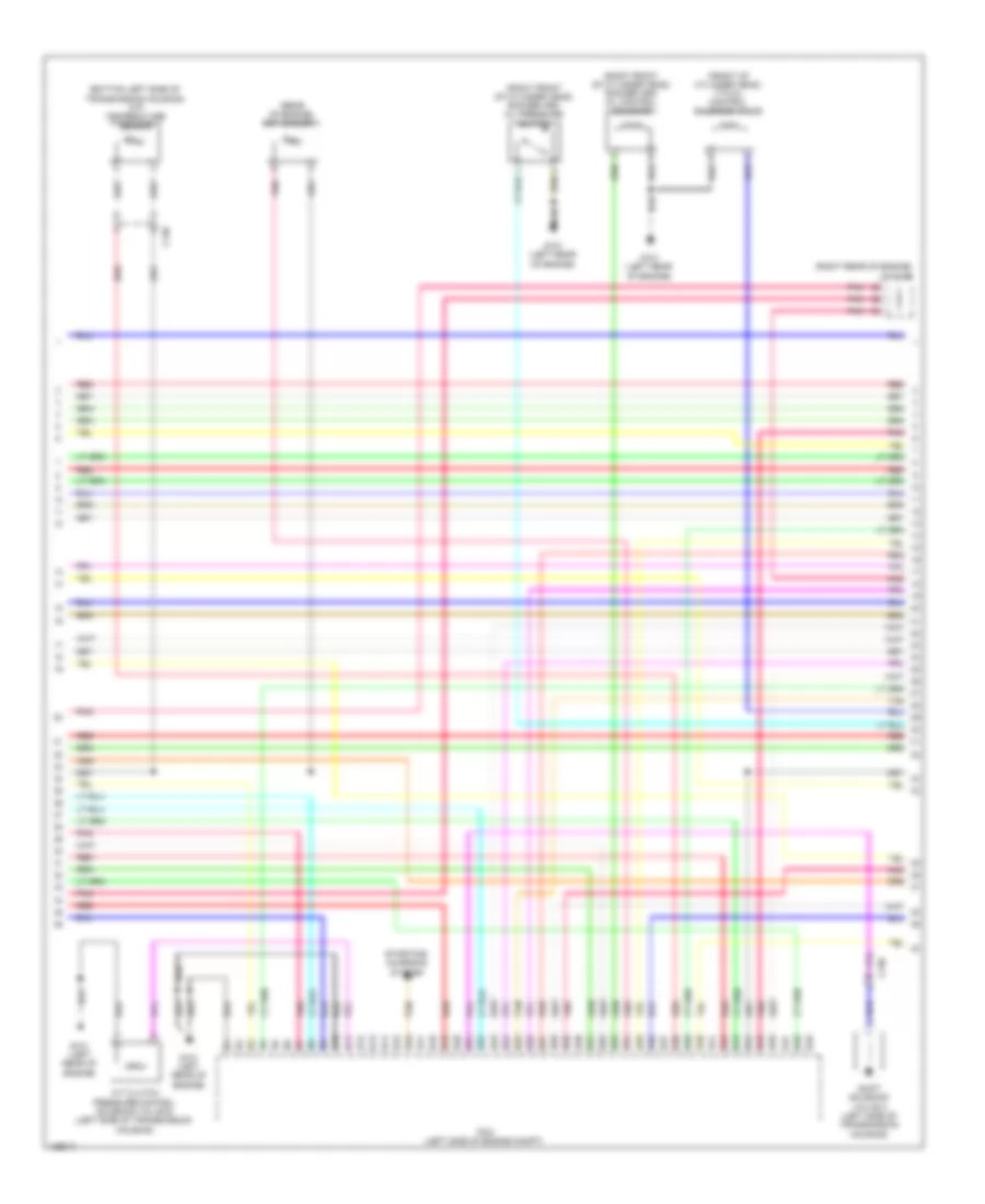
2.4L, Engine Performance Wiring Diagram (2 of 5) for Honda CR-V EX-L 2014
List of elements for 2.4L, Engine Performance Wiring Diagram (2 of 5) for Honda CR-V EX-L 2014:
- (top of fuel tank) fuel tank unit
- A/t clutch pressure control solenoid valve a (top of transmission housing)
- C130
- Cmp sensor a (right rear of cylinder head)
- Eld unit
- Evap canister purge valve (rear of engine)
- Fuse 1-6 100a
- Fuse 10a
- Fuse 15a
- Fuse 7.5a
- G101 (left rear of engine)
- G302 (under left headlight assembly)
- G603 (top of left "d" pillar)
- Hot at all times
- Hot in on or start
- Ignition coil relay
- Instrument cluster system
- J/c c134
- J/c c136 (right rear of engine)
- Maf sensor/ iat sensor (on intake air duct)
- Map sensor (on throttle body)
- Oil pressure switch (on right front of engine, above oil filter)
- Output shaft (counter shaft) speed sensor (right rear of transmission housing)
- Pnk
- Red
- Shift solenoid valve b (left side of transmission housing)
- Transmission fluid pressure switch a (2nd clutch) (top of transmission housing)
- Transmission fluid pressure switch b (3rd clutch)
- Under-dash fuse/relay box (under left end of dash)
- Under-hood fuse/ relay box (on left side of engine compt)
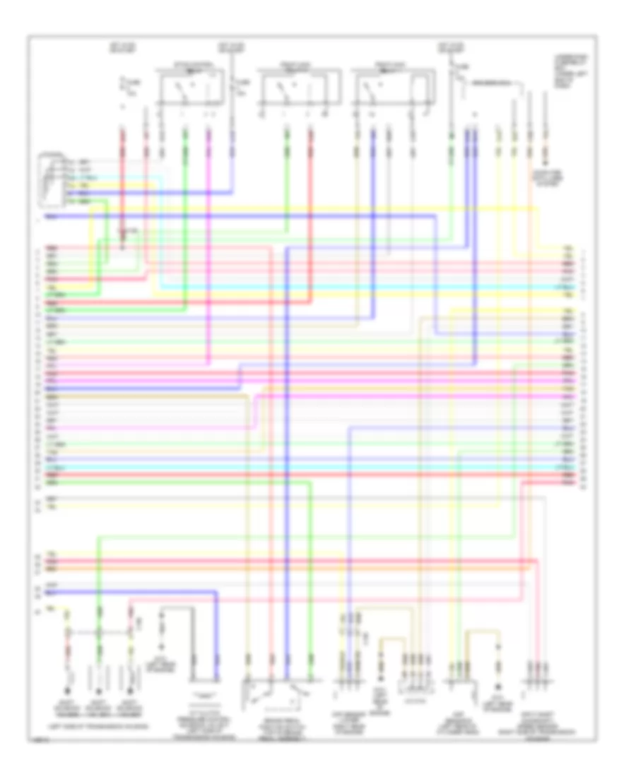
2.4L, Engine Performance Wiring Diagram (3 of 5) for Honda CR-V EX-L 2014
List of elements for 2.4L, Engine Performance Wiring Diagram (3 of 5) for Honda CR-V EX-L 2014:
- (bottom left side of transmission housing) atf temperature sensor
- (front of cylinder head) vtc oil control solenoid valve
- (rear of engine) ect sensor 1
- (right front of cylinder head) rocker arm oil control solenoid
- (right front of cylinder head) rocker arm oil pressure switch
- (right rear of engine) j/c c136
- A/t clutch pressure control solenoid valve b (left side of transmission housing)
- B10
- B11
- B12
- B13
- B14
- B15
- B16
- B17
- B18
- B19
- B20
- B21
- B22
- B23
- B24
- B25
- B26
- B27
- B28
- B29
- B30
- B31
- B32
- B33
- B34
- B35
- B36
- B37
- B38
- B39
- B40
- B41
- B42
- B43
- B44
- B45
- B46
- B47
- B48
- B49
- C130
- G101 (left rear of engine)
- Pcm (left side of engine compt)
- Pnk
- Red
- Shift solenoid valve a (left side of transmission housing)
- Starting/ charging system
- Tan
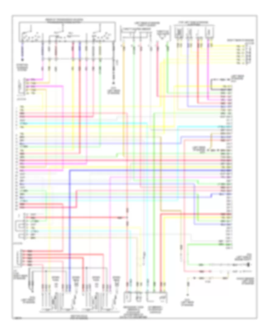
2.4L, Engine Performance Wiring Diagram (4 of 5) for Honda CR-V EX-L 2014
List of elements for 2.4L, Engine Performance Wiring Diagram (4 of 5) for Honda CR-V EX-L 2014:
- (left side of transmission housing)
- A/t clutch pressure control solenoid valve c (left side of transmission housing)
- B17
- Brake pedal position switch (top of brake pedal assembly)
- C126 red
- C13
- C130
- C135
- C16
- C20
- C24
- C25
- C34
- C35
- Ckp sensor (lower right rear of engine)
- Cmp sensor b (left rear of cylinder head)
- Computer data lines system
- D11
- D12
- D22
- D26
- Driver's micu
- Etcs control relay
- Fuse 10a
- Fuse 15a
- G101 (left rear of engine)
- Hot in on or start
- Input shaft (mainshaft) speed sensor (right side of transmission housing)
- J/c c134
- Pgm-fi main relay 1
- Pgm-fi main relay 2
- Pnk
- Red
- Shift solenoid valve c
- Shift solenoid valve d
- Shift solenoid valve e
- Tan
- Under-dash fuse/relay box (under left end of dash)
2.4L, Engine Performance Wiring Diagram (5 of 5) for Honda CR-V EX-L 2014
List of elements for 2.4L, Engine Performance Wiring Diagram (5 of 5) for Honda CR-V EX-L 2014:
- (left rear of engine) g101
- (left rear of engine) throttle body
- (rear of transmission housing) transmission range switch
- (right rear of engine)
- (top left side of engine) injectors
- 2-1
- A/f sensor 1 (on exhaust manifold)
- C10
- C11
- C12
- C13
- C131
- C132
- C14
- C15
- C16
- C17
- C18
- C19
- C20
- C21
- C22
- C23
- C24
- C25
- C26
- C27
- C28
- C29
- C30
- C31
- C32
- C33
- C34
- C35
- C36
- C37
- C38
- C39
- C40
- C41
- C42
- C43
- C44
- C45
- C46
- C47
- C48
- C49
- G101 (left rear of engine)
- G102 (left front of engine)
- Icm
- Ignition coils (top of engine)
- J/c c134
- J/c c136
- J/c c136 (right rear of engine)
- Knock sensor (left side of engine)
- Pcm (left side of engine compt)
- Pnk
- Red
- Secondary ho2s (sensor 2) (in exhaust, downstream of catalytic converter)
- Spark plug
- Starting/ charging system
- Tan
- Throttle actuator
- Throttle open sensor