ENGINE PERFORMANCE
2.4L
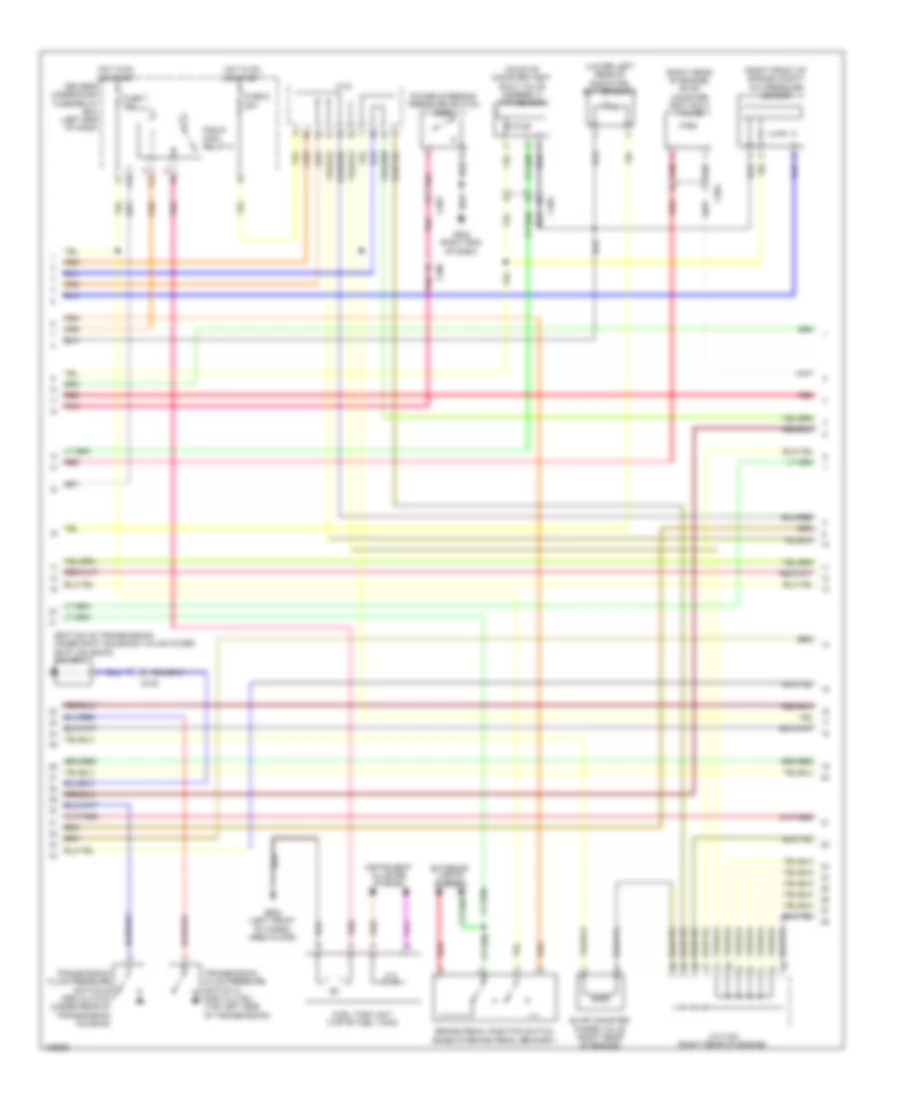
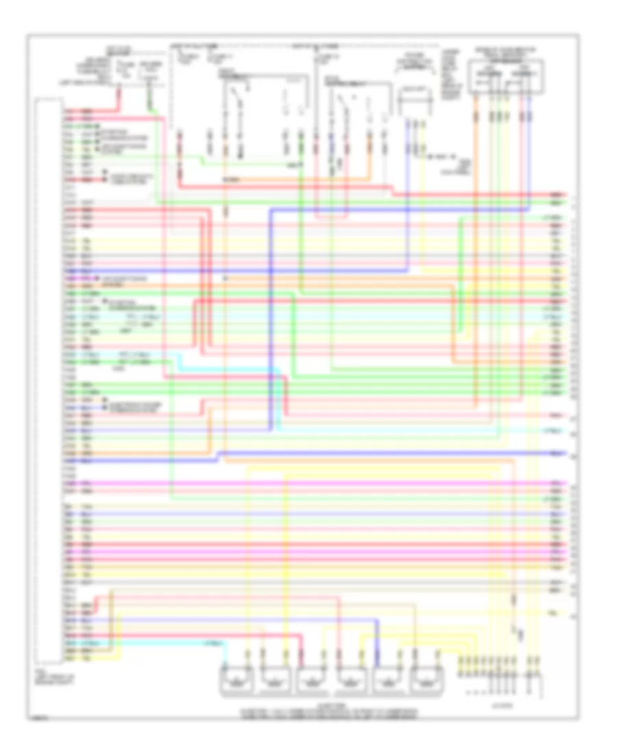
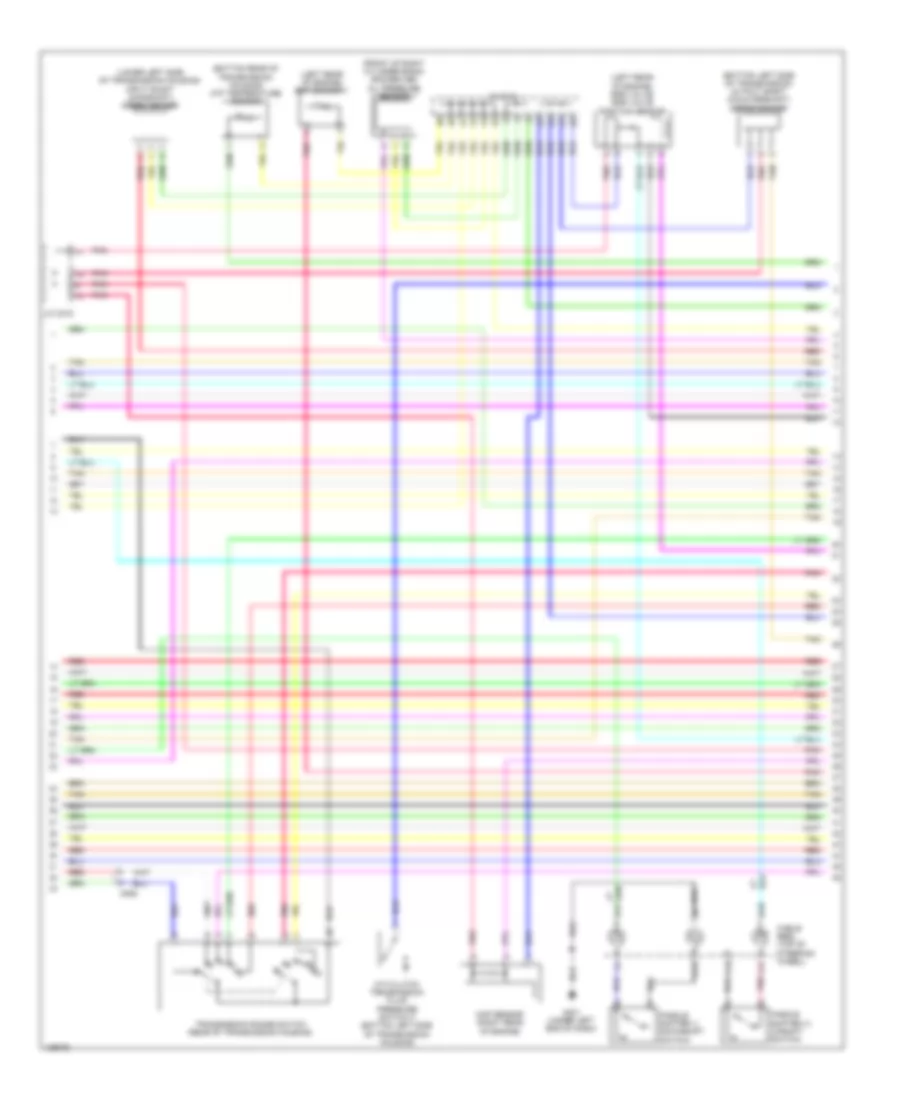
2.4L, Engine Performance Wiring Diagram (1 of 5) for Honda Crosstour EX-L 2014

List of elements for 2.4L, Engine Performance Wiring Diagram (1 of 5) for Honda Crosstour EX-L 2014:
- (b12 to b15 not used)
- (left front of engine compt) pcm
- (left kick panel) g302
- (top left rear of engine) g101
- A10
- A11
- A12
- A13
- A14
- A15
- A16
- A17
- A18
- A19
- A20
- A21
- A22
- A23
- A24
- A25
- A26
- A27
- A28
- A29
- A30
- A31
- A32
- A33
- A34
- A35
- A36
- A37
- A38
- A39
- A40
- A41
- A42
- A43
- A44
- A45
- A46
- A47
- A48
- A49
- Air conditioning system
- App sensor (base of accelerator pedal bracket)
- App sensor a
- App sensor b
- B10
- B11
- B16
- B17
- B18
- B19
- B20
- B21
- B22
- B23
- B24
- B25
- B26
- B27
- B28
- B29
- B30
- B31
- C101
- C106
- C306
- Computer data lines system
- Driver's j/b (left side of dash)
- Driver's under-dash fuse/relay box (left end of dash)
- Eld unit
- Etcs control relay
- F15
- Fuse 10 10a
- Fuse 17 15a
- Fuse 18 15a
- G101 (top left rear of engine)
- Hot at all times
- Hot in on or start
- Navigation system
- Oil pressure switch (near oil filter)
- Pgm-fi main relay 1
- Pnk
- Red
- Shift lock solenoid (base of shift lever assembly)
- Starting/ charging system
- To ignition coil relay (diagram 3 of 5)
- Transmission range switch (rear of transmission housing)
- Under-hood fuse/relay box (left rear of engine compt)
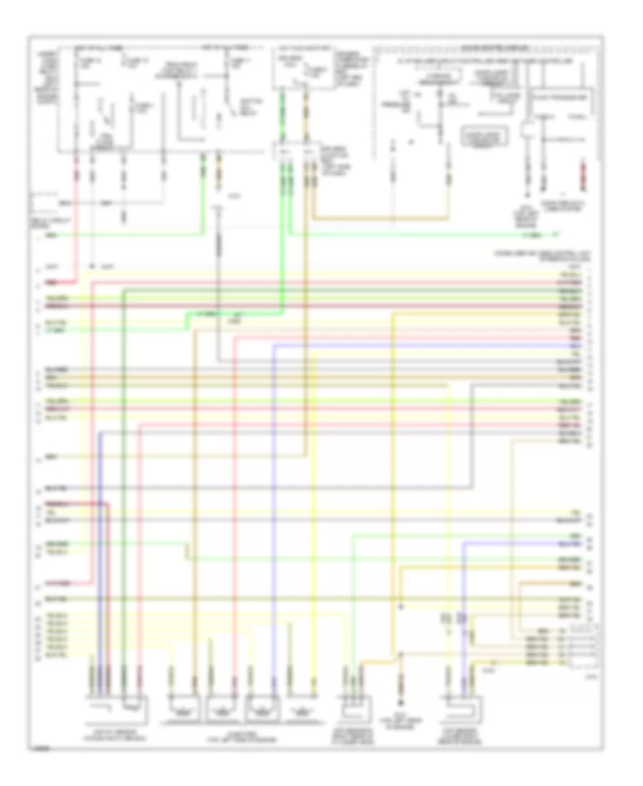
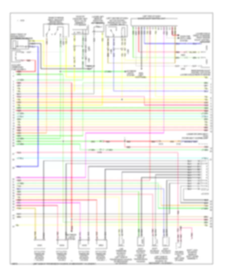
2.4L, Engine Performance Wiring Diagram (2 of 5) for Honda Crosstour EX-L 2014
List of elements for 2.4L, Engine Performance Wiring Diagram (2 of 5) for Honda Crosstour EX-L 2014:
- (bottom of transmission, under shift solenoid valve cover) shift solenoid valve a
- (lower left rear of radiator) ect sensor 2
- (on evap canister vent shut valve assembly) ftp sensor
- (right front of engine compt) a/c pressure sensor
- (right rear of engine) evap canister vent shut valve
- Brake pedal position switch (base of brake pedal bracket)
- C101
- C202
- C304
- C306
- Driver's under-dash fuse/relay box (left end of dash)
- Evap canister purge valve (right rear of engine)
- Exterior lights system
- F12
- F33
- Fuel tank unit (top of fuel tank)
- Fuse 7 15a
- Fuse 9 20a
- G105
- G203 (right end of dash)
- G602 (left front of cargo area floor)
- Hot in on or start
- Instrument cluster system
- J/c c103 (right rear of engine)
- Pgm-fi main relay 2
- Pnk
- Power steering pressure switch (psp)
- Red
- Transmission fluid pressure switch a (2nd clutch) (top left side of transmission)
- Transmission fluid pressure switch b (3rd clutch) (under rear of transmission housing)
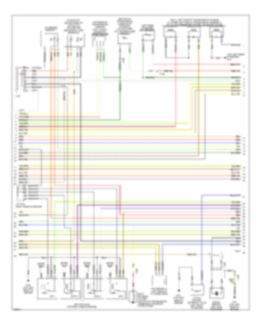
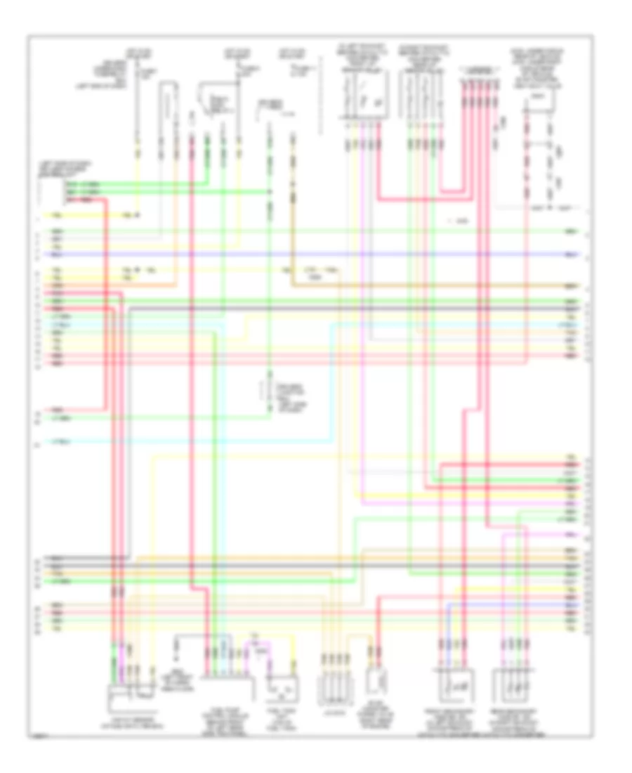
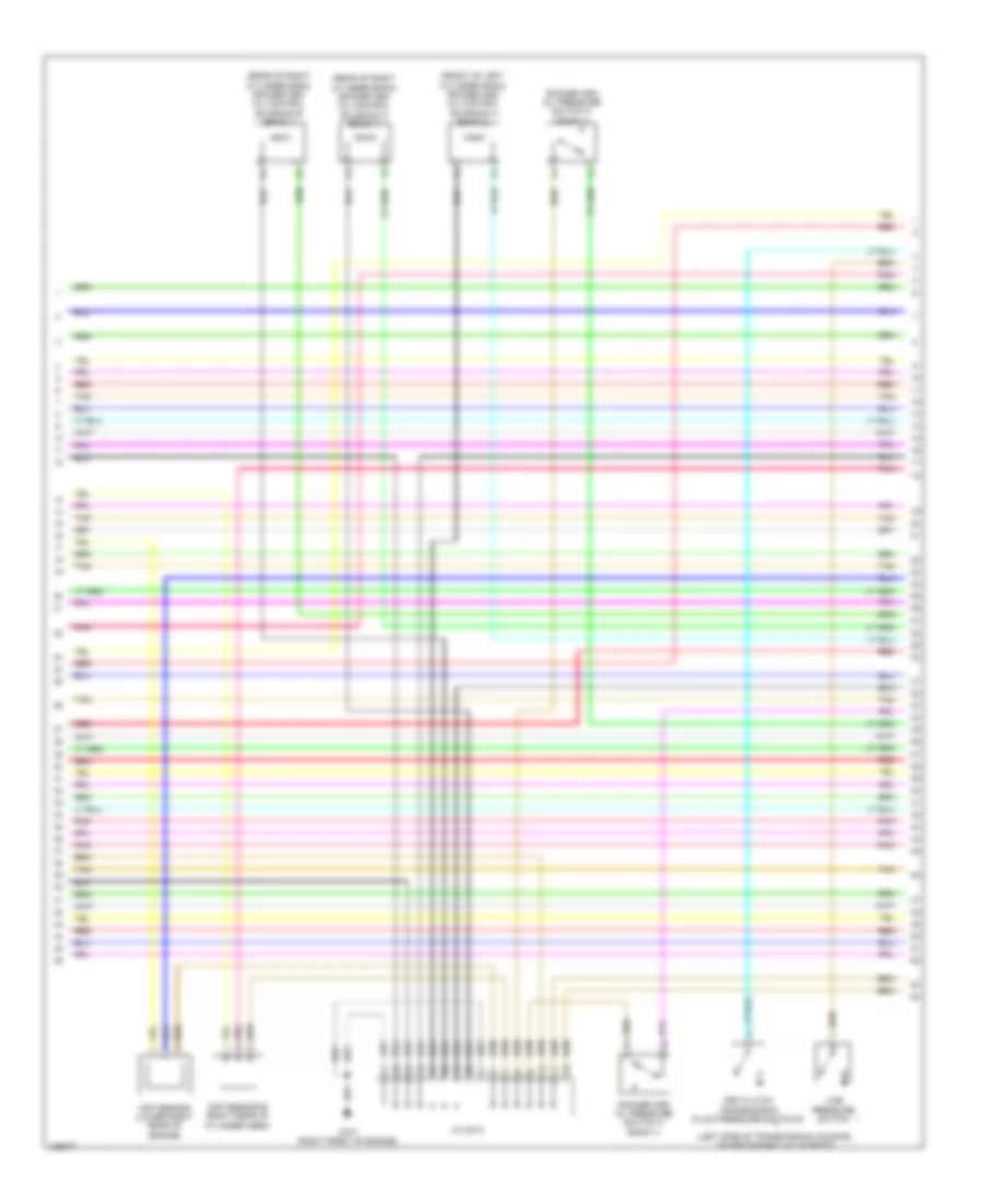
2.4L, Engine Performance Wiring Diagram (3 of 5) for Honda Crosstour EX-L 2014
List of elements for 2.4L, Engine Performance Wiring Diagram (3 of 5) for Honda Crosstour EX-L 2014:
- 5v stabilizer circuit/controller area network controller
- B13
- C101
- C104
- C306
- Ckp sensor (lower right rear of engine)
- Cmp sensor b (right rear of cylinder head)
- Compulsory turning off circuit
- Compulsory turning on circuit
- Computer data lines system
- Driver's junction box (left side of dash)
- Driver's micu
- Driver's under-dash fuse/relay box (left end of dash)
- F-can h
- F-can l
- F-can transceiver
- Fail safe circuit
- From pgm-fi main relay 1 (diagram 1 of 5)
- Fuse 11 15a
- Fuse 12 15a
- Fuse 15 10a
- Fuse 4 7.5a
- Fuse 5 7.5a
- G101 (top left rear of engine)
- Gauge control module
- Hot at all times
- Hot in on or start
- Ignition coil relay
- Immobilizer keyless control unit (steering column)
- Injectors (top left side of engine)
- Low oil pressure ind
- Maf/iat sensor (intake air filter box)
- Mil ind
- Pgm- fi sub relay
- Q16
- Red
- Relay circuit board
- Under- hood fuse/ relay box (left rear of engine compt)
- Warning drive circuit
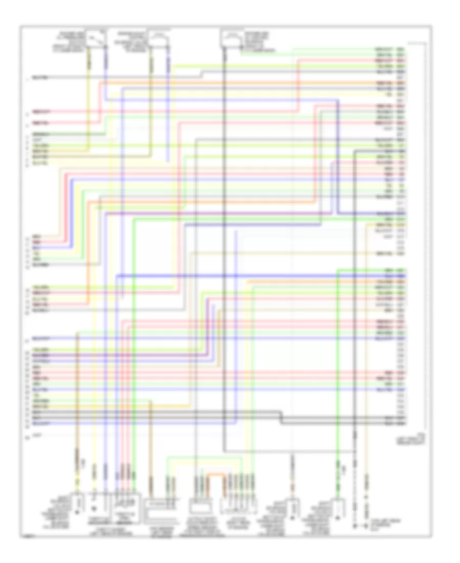
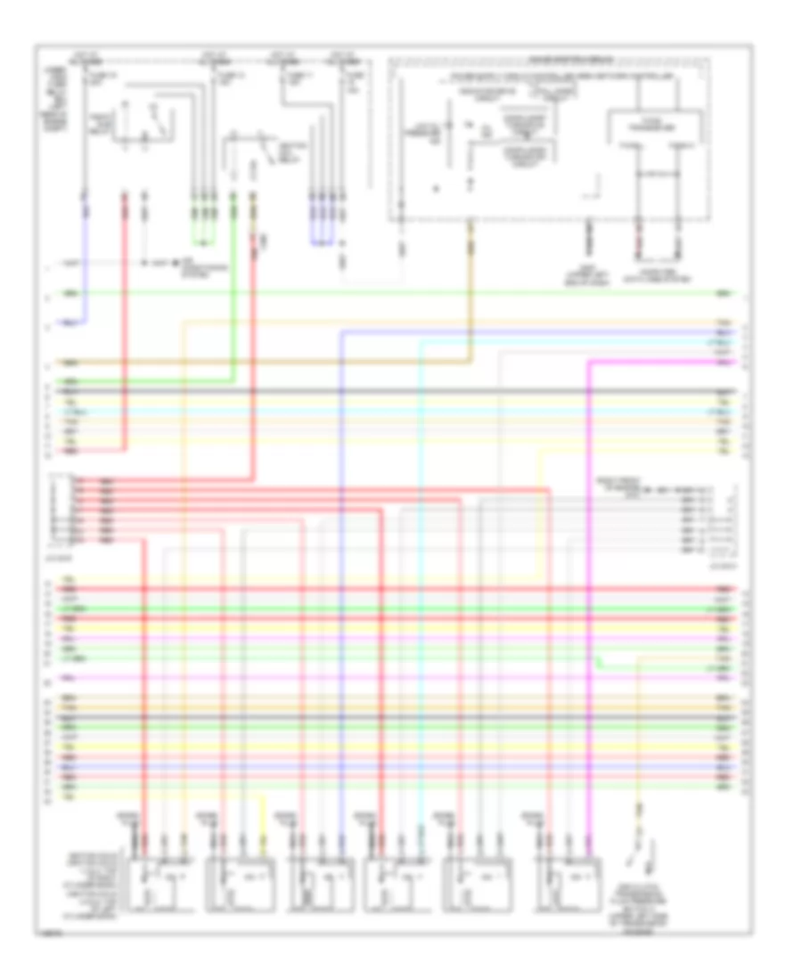
2.4L, Engine Performance Wiring Diagram (4 of 5) for Honda Crosstour EX-L 2014
List of elements for 2.4L, Engine Performance Wiring Diagram (4 of 5) for Honda Crosstour EX-L 2014:
- (b & c: left side of transmission housing) (a: upper left side of transmission assembly) a/t clutch pressure control solenoid valves
- (bottom of transmission, under shift solenoid valve cover) atf temperature sensor
- (in exhaust, downstream of catalytic converter) secondary ho2s (sensor 2)
- (left rear of engine) ect sensor 1
- (top left rear of engine) g101
- (top rear of transmission housing) input shaft (mainshaft) speed sensor
- A/f sensor (sensor 1)
- C101
- C105
- C107
- Cmp sensor a (left rear of cylinder head)
- G101 (top left rear of engine)
- G102 (top left front of engine)
- Icm 1
- Icm 2
- Icm 3
- Icm 4
- Ignition coils (top right side of engine)
- J/c c103 (right rear of engine)
- Knock sensor (left side of engine)
- N/a
- Red
- Shift solenoid valve e (bottom of transmission, under shift solenoid valve cover)
- Spark plug
- Vtc oil control solenoid valve (left front of engine)
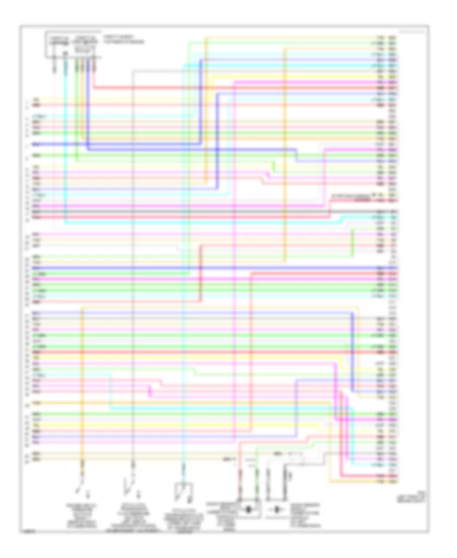
2.4L, Engine Performance Wiring Diagram (5 of 5) for Honda Crosstour EX-L 2014
List of elements for 2.4L, Engine Performance Wiring Diagram (5 of 5) for Honda Crosstour EX-L 2014:
- (bottom of transmission, under shift solenoid valve cover)
- (top left rear of engine) g101
- B32
- B33
- B34
- B35
- B36
- B37
- B38
- B39
- B40
- B41
- B42
- B43
- B44
- B45
- B46
- B47
- B48
- C10
- C105
- C11
- C12
- C13
- C14
- C15
- C16
- C17
- C18
- C19
- C20
- C21
- C22
- C23
- C24
- C25
- C26
- C27
- C28
- C29
- C30
- C31
- C32
- C33
- C34
- C35
- C36
- C37
- C38
- C39
- C40
- C41
- C42
- C43
- C44
- C45
- C46
- C47
- C48
- Engine mount control solenoid valve (left front of engine)
- J/c c103 (right rear of engine)
- Map sensor (left rear of engine)
- Output shaft (countershaft) speed sensor (top right side of transmission housing)
- Pcm (left front of engine compt)
- Red
- Rocker arm oil control solenoid (front of cylinder bank)
- Shift solenoid valve b
- Shift solenoid valve c (bottom of transmission, under shift solenoid valve cover)
- Shift solenoid valve d (bottom of transmission, under shift solenoid valve cover)
- Throttle actuator
- Throttle body (left rear of engine)
- Throttle open sensor
3.5L
3.5L, Engine Performance Wiring Diagram (1 of 7) for Honda Crosstour EX-L 2014
List of elements for 3.5L, Engine Performance Wiring Diagram (1 of 7) for Honda Crosstour EX-L 2014:
- (base of accelerator pedal bracket) app sensor
- (injector 1, 2 & 3: under intake manifold, on right cylinder bank) (injector 4, 5 & 6: under intake manifold, on left cylinder bank)
- A10
- A11
- A12
- A13
- A14
- A15
- A16
- A17
- A18
- A19
- A20
- A21
- A22
- A23
- A24
- A25
- A26
- A27
- A28
- A29
- A30
- A31
- A32
- A33
- A34
- A35
- A36
- A37
- A38
- A39
- A40
- A41
- A42
- A43
- A44
- A45
- A46
- A47
- A48
- A49
- A50
- A51
- Air conditioning system
- App sensor a
- App sensor b
- Atp-p
- B10
- B11
- B12
- B13
- B14
- B15
- B16
- B17
- B18
- B19
- B20
- B21
- C408
- C506
- C507
- Computer data lines system
- Driver's micu
- Driver's under-dash fuse/relay box (left end of dash)
- Eld unit
- Electronic power steering system
- Etcs control relay
- F15
- F23
- Fuse 10a
- Fuse 17 15a
- Fuse 18 15a
- Fuse 8 20a
- G302 (left kick panel)
- Hot at all times
- Hot in on or start
- Injectors
- J/c c016
- Pcm (left front of engine compt)
- Pgm-fi main relay 1
- Pnk
- Power distribution system
- Red
- Starting/ charging system
- Tan
- Under- hood fuse/ relay box (left rear of engine compt)
3.5L, Engine Performance Wiring Diagram (2 of 7) for Honda Crosstour EX-L 2014
List of elements for 3.5L, Engine Performance Wiring Diagram (2 of 7) for Honda Crosstour EX-L 2014:
- (base of brake pedal bracket) brake pedal position switch
- (left center of dash) active control engine mount (acm) control relay
- (left end of dash) engine mount control unit
- (left side of transmission housing, on secondary valve body)
- (lower left rear of radiator) ect sensor 2
- (lower middle front of engine) front engine mount control actuator
- (on evap canister vent shut valve assembly) ftp sensor
- (right front of engine compt) a/c pressure sensor
- (under driver's seat) (4wd) power seat control unit
- 4wd
- A/t clutch pressure control solenoid valve a
- A/t clutch pressure control solenoid valve b
- A/t clutch pressure control solenoid valve c
- A/t clutch pressure control solenoid valve d
- Auxiliary under-dash fuse holder a
- B35
- C142
- C403
- C408
- C412
- C502
- C503
- C507
- C603
- Computer data lines system
- Driver's junction box (left side of dash)
- Exterior lights system
- G302 (left kick panel)
- J/c c015
- Line pressure solenoid valve a (left side of transmission housing, on secondary valve body)
- Pnk
- Rear engine mount control actuator (lower middle rear of engine)
- Red
- Shift lock solenoid (base of shift lever assembly)
- Shift solenoid valve a
- Shift solenoid valve b
- Shift solenoid valve c (lower left side of transmission housing)
- Tan
3.5L, Engine Performance Wiring Diagram (3 of 7) for Honda Crosstour EX-L 2014
List of elements for 3.5L, Engine Performance Wiring Diagram (3 of 7) for Honda Crosstour EX-L 2014:
- (2wd: under middle rear of vehicle) (4wd: under right middle rear of vehicle) evap canister vent shut valve
- (in left exhaust, before catalytic converter) front a/f sensor (b2, s1)
- (in right exhaust, before catalytic converter) rear a/f sensor (b1, s1)
- (left side of dash) keyless access control unit
- 4wd
- B11
- B21
- C18
- C506
- C507
- C603
- C805
- Driver"s micu
- Driver's junction box (left side of dash)
- Driver's under-dash fuse/relay box (left end of dash)
- Evap canister purge valve (right rear of engine)
- F12
- F33
- Front secondary ho2s (b2, s2) (in left exhaust, downstream of catalytic converter)
- Fuel pump control module (behind front of left rear side trim panel)
- Fuel tank unit (top of fuel tank)
- Fuse 11 7.5a
- Fuse 7 15a
- Fuse 9 20a
- G602 (left front of cargo area floor)
- Hot in on or start
- J/c c015
- J/c c016
- Maf/iat sensor (intake air filter box)
- Pgm-fi main relay 2
- Pnk
- Q16
- Rear secondary ho2s (b1, s2) (in right exhaust, downstream of catalytic converter)
- Red
- Tan
3.5L, Engine Performance Wiring Diagram (4 of 7) for Honda Crosstour EX-L 2014
List of elements for 3.5L, Engine Performance Wiring Diagram (4 of 7) for Honda Crosstour EX-L 2014:
- (ignition coils 4 5 & 6: top of left cylinder bank)
- (right front of engine) g101
- 2nd clutch transmission fluid pressure switch a (upper left side of transmission housing)
- Air conditioning system
- C506
- Compulsory turning off circuit
- Compulsory turning on circuit
- Computer data lines system
- F-can h
- F-can l
- F-can transceiver
- Fall safe circuit
- Fuse 11 15a
- Fuse 12 15a
- Fuse 15a
- Fuse 19 20a
- G402 (upper left end of dash)
- Gauge control module
- Hot at all times
- Icm
- Ignition coil relay
- Ignition coils (ignition coils 1 2 & 3: top of right cylinder bank)
- Indicator drive circuit
- J/c c013
- J/c c016
- Low oil pressure ind
- Mil ind
- Nca
- Pgm-fi sub relay
- Red
- Spark plug
- Tan
- Under- hood fuse/ relay box (left rear of engine compt)
3.5L, Engine Performance Wiring Diagram (5 of 7) for Honda Crosstour EX-L 2014
List of elements for 3.5L, Engine Performance Wiring Diagram (5 of 7) for Honda Crosstour EX-L 2014:
- (bottom left side of transmission) output shaft (countershaft) speed sensor
- (bottom rear of transmission housing) atf temperature sensor
- (front of right cylinder bank) rocker arm oil pressure sensor
- (left rear of engine) ect sensor 1
- (left rear of engine) egr valve/ egr valve position sensor
- (lower left side of transmission housing) input shaft (mainshaft) speed sensor
- 4th clutch transmission fluid pressure switch c (bottom left side of transmission housing)
- A17
- A18
- C11
- C12
- C506
- Cable reel (top of steering wheel)
- G401 (under left end of dash)
- J/c c013
- J/c c015
- Map sensor (right rear of engine)
- Paddle shifter (+) (upshift switch)
- Paddle shifter (-) (downshift switch)
- Pnk
- Red
- Tan
- Transmission range switch (rear of transmission housing)
3.5L, Engine Performance Wiring Diagram (6 of 7) for Honda Crosstour EX-L 2014
List of elements for 3.5L, Engine Performance Wiring Diagram (6 of 7) for Honda Crosstour EX-L 2014:
- (front of left cylinder bank) rocker arm oil control solenoid a (bank 2)
- (left side of transmission housing, on secondary valve body)
- (rear of right cylinder bank) rocker arm oil control solenoid a (bank 1)
- (rear of right cylinder bank) rocker arm oil control solenoid b (bank 1)
- 3rd clutch transmission fluid pressure switch b
- Ckp sensor (lower right rear of engine)
- Cmp sensor b (right rear of cylinder head)
- G101 (right front of engine)
- J/c c014
- Line pressure switch
- Pnk
- Red
- Rocker arm oil pressure switch a (bank 1)
- Rocker arm oil pressure switch a (bank 2)
- Tan
3.5L, Engine Performance Wiring Diagram (7 of 7) for Honda Crosstour EX-L 2014
List of elements for 3.5L, Engine Performance Wiring Diagram (7 of 7) for Honda Crosstour EX-L 2014:
- (top rear of engine)
- 5th clutch transmission fluid pressure switch d (upper left side of transmission housing)
- 6th clutch transmission fluid pressure switch e (left side of transmission housing, on secondary valve body)
- B22
- B23
- B24
- B25
- B26
- B27
- B28
- B29
- B30
- B31
- B32
- B33
- B34
- B35
- B36
- B37
- B38
- B39
- B40
- B41
- B42
- B43
- B44
- B45
- B46
- B47
- B48
- B49
- B50
- B51
- C10
- C11
- C12
- C13
- C14
- C15
- C16
- C17
- C18
- C19
- C20
- C21
- C22
- C23
- C24
- C25
- C26
- C27
- C28
- C29
- C30
- C31
- C32
- C33
- C34
- C35
- C36
- C37
- C38
- C39
- C40
- C41
- C42
- C43
- C44
- C45
- C46
- C47
- C48
- C49
- C901
- Knock sensor (bank 1) (under intake manifold, on right cylinder bank)
- Knock sensor (bank 2) (under intake manifold, on left cylinder bank)
- Pcm (left front of engine compt)
- Pnk
- Red
- Rocker arm oil pressure switch b (bank 1) (rear of right cylinder bank)
- Starting/charging system
- Tan
- Throttle actuator
- Throttle body
- Throttle open sensor