ENGINE PERFORMANCE
3.5L
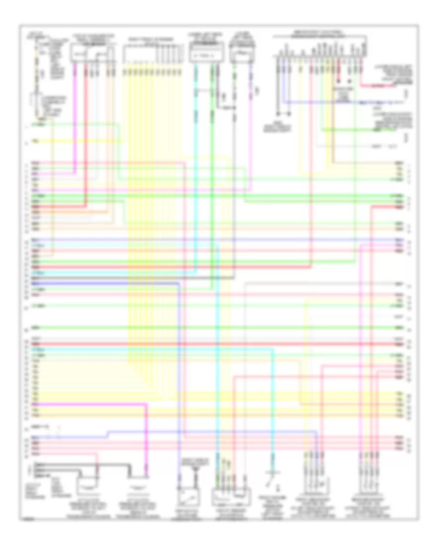
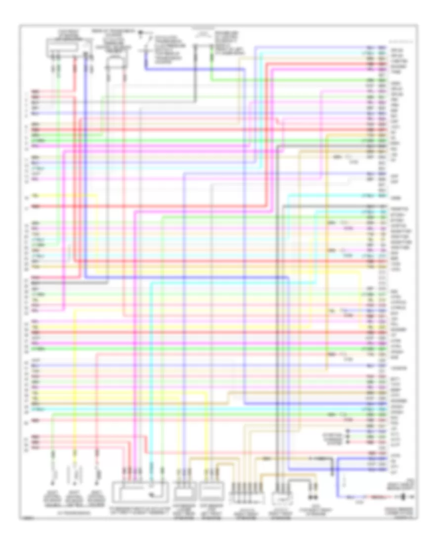
3.5L, Engine Performance Wiring Diagram (1 of 6) for Honda Pilot EX-L 2014

List of elements for 3.5L, Engine Performance Wiring Diagram (1 of 6) for Honda Pilot EX-L 2014:
- (right side of engine compt) g202
- A10
- A11
- A12
- A13
- A14
- A15
- A16
- A17
- A18
- A19
- A20
- A21
- A22
- A23
- A24
- A25
- A26
- A27
- A28
- A29
- A30
- A31
- A32
- A33
- A34
- A35
- A36
- A37
- A38
- A39
- A40
- A41
- A42
- A43
- A44
- A45
- A46
- A47
- A48
- A49
- Acc
- Air conditioning system
- Anti-theft system
- Apsa
- Apsb
- Atpp
- B10
- B11
- B12
- B13
- B14
- B15
- B16
- B17
- B18
- B19
- B20
- B21
- Barometer sensor
- Bksw
- Bkswnc
- Brake pedal position switch (top of brake pedal assembly)
- C102
- Canh
- Canl
- Ckpout
- Cmpout
- Computer data lines system
- Cooling fans system
- Cssama
- Cssamc
- D3sw
- Ect2
- Eld
- Eld unit
- Etcs control relay
- Etcsrly
- F17
- F25
- F30
- Fanh
- Fanl
- Ftp
- Fuse 16 7.5a
- Fuse 18 15a
- Fuse 19 15a
- Fuse 21 15a
- Fuse 7.5a
- G101 (top right front of engine)
- Hot at all times
- Hot in on or start
- Ignition coil relay
- Igp
- Igpls5
- Igpls6
- Imofpr
- Imtm
- Inj1
- Inj2
- Inj3
- Inj4
- Inj5
- Inj6
- Injectors 1, 2 & 3 (under intake manifold, in right cylinder bank)
- Injectors 4, 5 & 6 (under intake manifold, in left cylinder bank)
- J/c c112 (right front of engine)
- J/c c113 (right front of engine)
- Lg3
- Lsb
- Lsc
- Mrly
- Nca
- Nep
- Pcm (right side of engine compt)
- Pg2
- Pgm-fi main relay 1
- Pnk
- Power distribution system
- Pspsw
- Red
- S net
- Scs
- Sg3
- Sg4
- Sg7
- Shift interlock system starting/charging system
- Sho2sb2
- Sls
- Sound systems
- Starting/ charging & anti-theft systems
- Starting/charging system
- Strld
- Strly
- Sts
- Subrly
- Tan
- Tpsa
- Under-dash fuse/relay box (left end of dash)
- Under-hood fuse/relay box (right rear of engine compt)
- Vbsol1
- Vbsol2
- Vbum
- Vcc3
- Vcc4
- Vcc5
- Vcc7
- Vcentb2
- Vcmswc
- Vg+
- Vg-
- Vsb1
- Vsb2
- Vssout
- Vsv
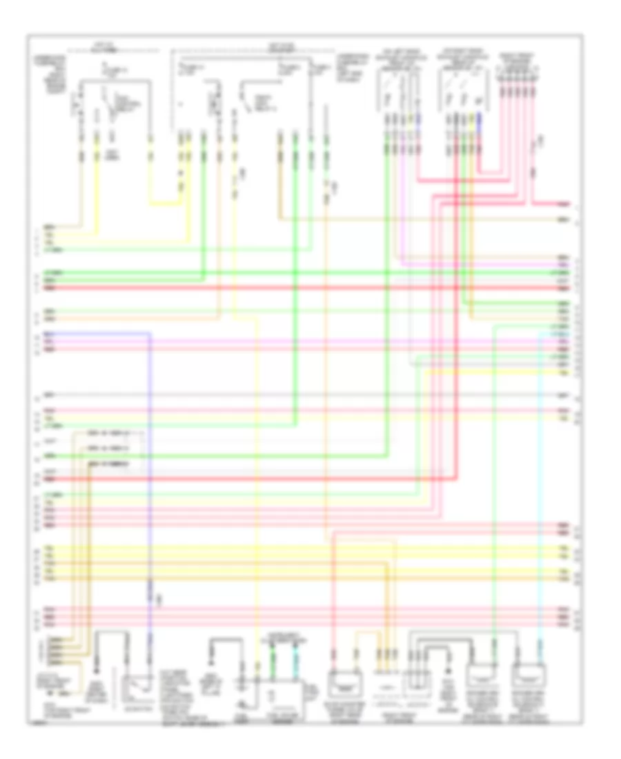
3.5L, Engine Performance Wiring Diagram (2 of 6) for Honda Pilot EX-L 2014
List of elements for 3.5L, Engine Performance Wiring Diagram (2 of 6) for Honda Pilot EX-L 2014:
- (behind right kick panel) engine mount control unit
- (lower left rear of radiator) ect sensor 2
- (lower middle left side of engine) front engine mount control actuator
- (lower middle right side of engine) rear engine mount control actuator
- (right front of engine) j/c c111
- (right side of engine compt) g202
- (top of accelerator pedal assembly) app sensor
- (under left rear of vehicle) ftp sensor
- A/t clutch pressure control solenoid valve b (rear of transmission housing)
- A/t clutch pressure control solenoid valve c (top of transmission housing)
- Auxiliary under- hood fuse/ relay box (left side of engine compt)
- C102
- C201
- C301
- C302
- C306
- Can h
- Can l
- Ckp
- Cmp
- Computer data lines system
- F31
- Front rocker arm oil pressure switch (left front of engine)
- Front secondary ho2s (b2, s2) (in left bank exhaust, downstream of catalytic converter)
- Fuse 20a
- G101 (top right front of engine)
- G16
- G202 (right side of engine compt)
- Hot at all times
- Iat
- Ig1
- Igsol
- J/c c113 (right front of engine)
- Maf
- Maf/iat sensor (on manifold air intake duct)
- Nca
- Pnk
- Psp switch (on power steering pump)
- Rear secondary ho2s (b1, s2) (in right bank exhaust, downstream of catalytic converter)
- Red
- Solfm
- Solfp
- Solrly
- Solrm
- Solrp
- Tan
- Under-dash fuse/relay box (left end of dash)
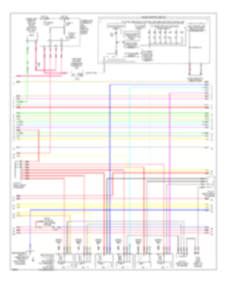
3.5L, Engine Performance Wiring Diagram (3 of 6) for Honda Pilot EX-L 2014
List of elements for 3.5L, Engine Performance Wiring Diagram (3 of 6) for Honda Pilot EX-L 2014:
- (not used)
- (on left bank exhaust manifold) front a/f sensor (b2, s1)
- (on right bank exhaust manifold) rear a/f sensor (b1, s1)
- (right front of engine)
- (right front of engine) j/c c112
- A/t gear position indicator panel light/park pin switch/ d3 switch (park pin switch: base of shift lever assembly)
- Acm control relay
- C102
- C303
- C307
- D3 switch
- E27
- E28
- Evap canister purge valve (right rear of engine)
- F10
- F15
- F24
- Fuel gauge sender
- Fuel pump
- Fuel tank unit
- Fuse 10 7.5a
- Fuse 12 10a
- Fuse 2 20a
- Fuse 3 10a
- G101 (top right front of engine)
- G403 (right center of dash)
- G503 (base of left "c" pillar)
- Hot at all times
- Hot in on or start
- Instrument cluster system
- J/c c112 (right front of engine)
- J/c c113
- J/c c114
- Nca
- Pgm-fi main relay 2
- Pnk
- Red
- Rocker arm oil control solenoid a (bank 1) (rear of right cylinder bank)
- Rocker arm oil control solenoid b (bank 1) (rear of right cylinder bank)
- Tan
- Under-dash fuse/relay box (left end of dash)
- Under-hood fuse/relay box (right rear of engine compt)
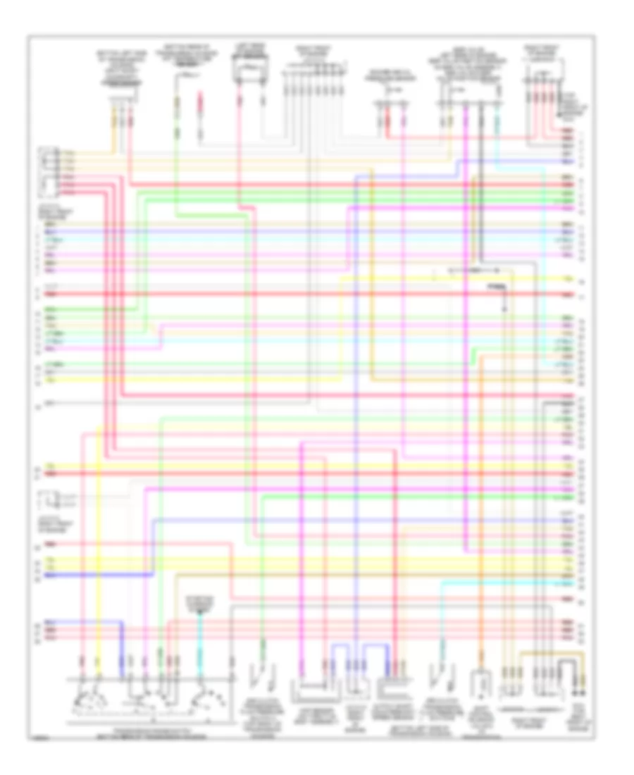
3.5L, Engine Performance Wiring Diagram (4 of 6) for Honda Pilot EX-L 2014
List of elements for 3.5L, Engine Performance Wiring Diagram (4 of 6) for Honda Pilot EX-L 2014:
- (left end of dash)
- (under left rear of vehicle) evap canister vent shut valve
- 10v stabilizer circuit
- 5v stabilizer circuit/controller area network controller
- A/t gear position indicator dimming circuit
- A/t gear position indicator drive circuit
- Back up
- C102
- C306
- Compulsory turning off circuit
- Compulsory turning on circuit
- Computer data lines system
- F16
- F18
- Fail-safe circuit
- Fast controller area network transceiver
- Fuse 11 15a
- Fuse 23 10a
- G101 (top right front of engine)
- Gauge control module
- Hot at all times
- Icm
- Ignition coils 1, 2, 3, 4, 5 & 6 (1, 2 & 3: top of right cylinder bank) (4, 5 & 6: top of left cylinder bank)
- Indicator drive circuit
- J/c c111 (right front of engine)
- J/c c112 (right front of engine)
- J/c c113 (right front of engine)
- Micu
- Mil ind
- Pgm fi sub relay
- Pnk
- Rear rocker arm oil pressure switch (right rear of engine)
- Red
- Spark plug
- Tan
- Trunk, tailgate, fuel doors system
- Under-dash fuse/relay box
- Under-hood fuse/relay box (right rear of engine compt)
3.5L, Engine Performance Wiring Diagram (5 of 6) for Honda Pilot EX-L 2014
List of elements for 3.5L, Engine Performance Wiring Diagram (5 of 6) for Honda Pilot EX-L 2014:
- (bottom left side of transmission housing)
- (bottom left side of transmission housing) input shaft (mainshaft) speed sensor
- (bottom rear of transmission housing) atf temperature sensor
- (egr valve: left rear of engine) (egr valve position sensor: on egr valve assembly) egr valve & egr valve position sensor
- (left rear of engine) ect sensor 1
- (right front of engine)
- (right front of engine) j/c c113
- (right front of engine) j/c c114
- 2nd clutch transmission fluid pressure switch a (top front of transmission housing)
- 3rd clutch transmission fluid pressure switch b
- G101 (top right front of engine)
- J/c c111
- J/c c112
- J/c c113 (right front of engine)
- Map sensor (on throttle body assembly)
- Nca
- Output shaft (countershaft) speed sensor
- Pnk
- Red
- Rocker arm oil pressure sensor
- Shift control solenoid valve d (in transmission)
- Starting/ charging system
- Tan
- Transmission range switch (bottom rear of transmission housing)
3.5L, Engine Performance Wiring Diagram (6 of 6) for Honda Pilot EX-L 2014
List of elements for 3.5L, Engine Performance Wiring Diagram (6 of 6) for Honda Pilot EX-L 2014:
- (in transmission)
- (rear of transmission housing) a/t clutch pressure control solenoid valve a
- (top front of engine) imt actuator
- 4th clutch transmission fluid pressure switch c (top rear of transmission housing)
- Afshtcb1
- Afshtcb2
- Altc
- Altf
- Altl
- Atp1
- Atp2
- Atpd
- Atpfwd
- Atpn
- Atpr
- Atprvs
- B22
- B23
- B24
- B25
- B26
- B27
- B28
- B29
- B30
- B31
- B32
- B33
- B34
- B35
- B36
- B37
- B38
- B39
- B40
- B41
- B42
- B43
- B44
- B45
- B46
- B47
- B48
- B49
- C10
- C102
- C11
- C12
- C13
- C14
- C15
- C151
- C152
- C16
- C17
- C18
- C19
- C20
- C21
- C22
- C23
- C24
- C25
- C26
- C27
- C28
- C29
- C30
- C31
- C32
- C33
- C34
- C35
- C36
- C37
- C38
- C39
- C40
- C41
- C42
- C43
- C44
- C45
- C46
- C47
- C48
- C49
- Ckp
- Ckp sensor (lower right rear of engine)
- Cmp
- Cmp sensor (top left front of engine)
- Cssa
- Cssb
- Cssc
- Ect1
- Egr
- Egrp
- Etcsm+
- Etcsm-
- G101 (top right front of engine)
- Iat
- Ig1
- Ig1etcs
- Igpls1
- Igpls2
- Igpls3
- Igpls4
- Imt+
- Imt-
- Ipb1
- Ipb2
- J/c c111 (right front of engine)
- J/c c112 (right front of engine)
- Knock sensor (under intake manifold)
- Lg1
- Lg2
- Lsa
- Map
- Nca
- Op2sw
- Op3sw
- Op4sw
- Pcm (right side of engine compt)
- Pcs
- Pg1
- Pgmetcs
- Pnk
- Poil
- Red
- Rocker arm oil control solenoid a (bank 2) (front of left cylinder bank)
- Sg1
- Sg2
- Sg5
- Sha
- Shb
- Shc
- Shd
- Shift control solenoid valve a
- Shift control solenoid valve b
- Shift control solenoid valve c
- Sho2sb1
- So2sgb1
- So2sgb2
- So2shtcb1
- So2shtcb2
- Starting/ charging system
- Tan
- Tatf
- Tp sensor/throttle actuator (on throttle body assembly)
- Tpsb
- Vcc1
- Vcc2
- Vcc6
- Vcentb2
- Vcmswb