ENGINE PERFORMANCE
4.4L
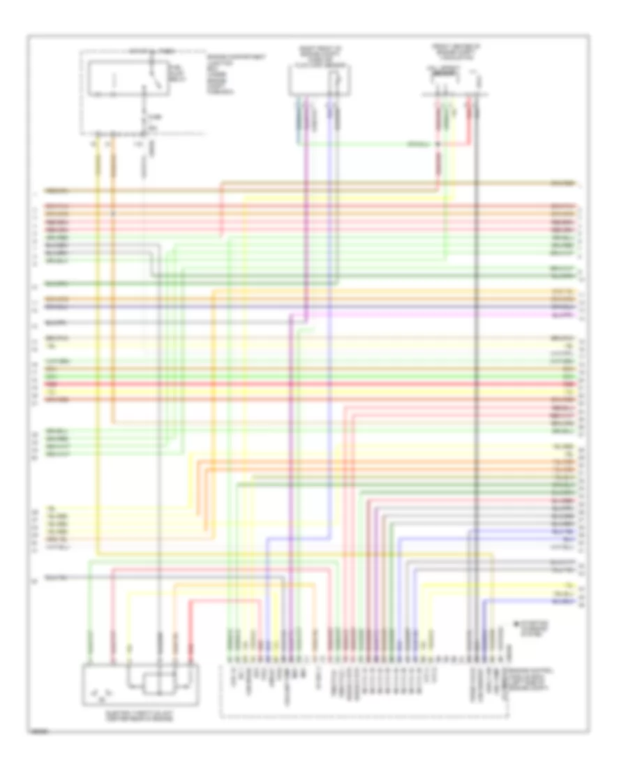
4.4L, Engine Performance Wiring Diagram (1 of 5) for Land Rover Discovery 3 HSE 2009

List of elements for 4.4L, Engine Performance Wiring Diagram (1 of 5) for Land Rover Discovery 3 HSE 2009:
- (not used)
- 5v ref 4
- Alt monitor
- C0570l
- C0634b
- Cam a gnd
- Cam a+
- Cam b gnd
- Cam b+
- Camshaft position sensor a (right rear of engine)
- Camshaft position sensor b (right rear of engine)
- Coil 1b
- Coil 2a
- Coil 2b
- Coil 3a
- Coil 3b
- Coil 4a
- Coil 4b
- Crank +
- Crank -
- Crankshaft position sensor (left side of engine)
- Egr 1
- Egr 2
- Egr 4
- Egr modulator valve
- Engine compartment junction box (under engine compt fuse box)
- Engine control module (ecm) (left side of engine compt)
- Engine control module relay
- Engine coolant temperature sensor (top of engine)
- Fuel temp
- Fuse 10a
- Fuse 15a
- Fuse 20a
- Fuse 5a
- Hot at all times
- Knock 1a +
- Knock 1a -
- Knock 1b +
- Knock 1b -
- Knock sensor (right front of engine)
- Left
- Maf gnd
- Nca
- Oil temp
- Red
- Right
- Sen gnd 5
- Sen gnd 6
- Sensor gnd 3
- Sensor gnd 4
- Starting/ charging system
- Uhego a gnd
- Uhego a sig
- Uhego b gnd
- Uhego b sig
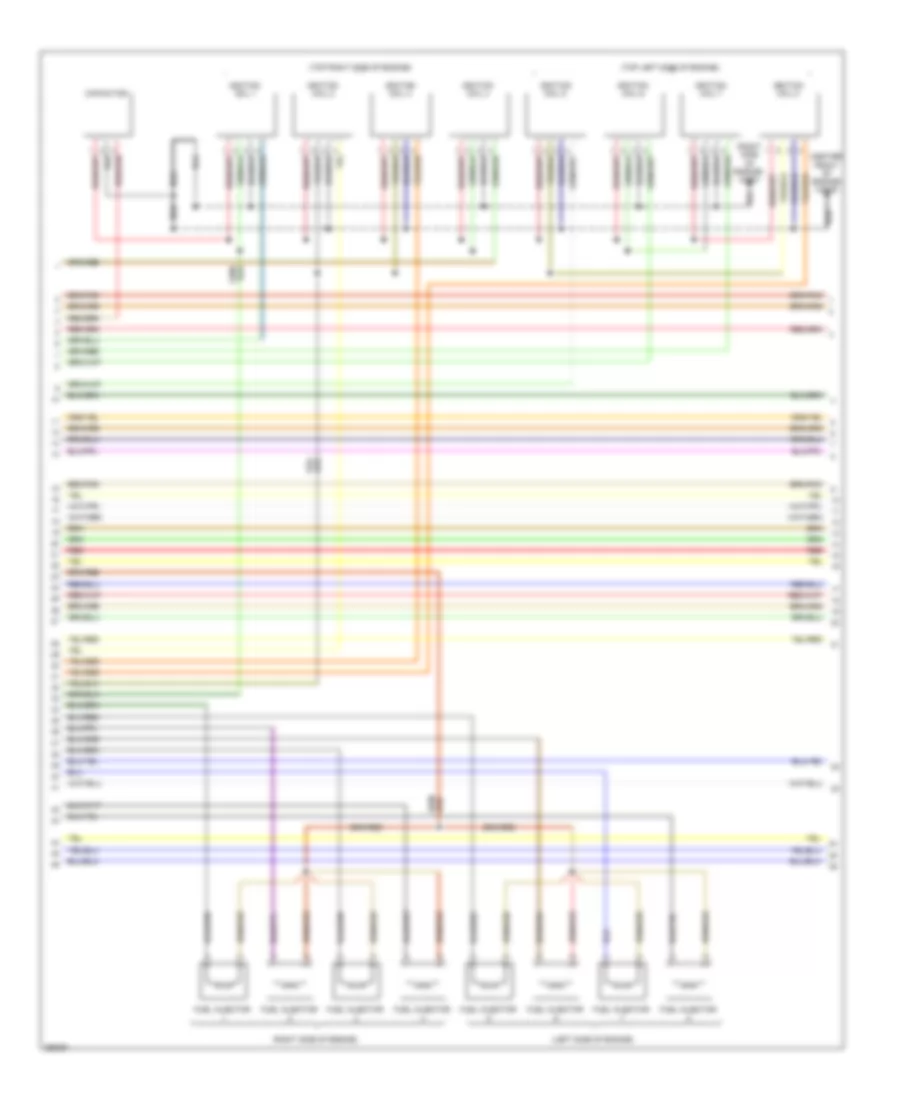
4.4L, Engine Performance Wiring Diagram (2 of 5) for Land Rover Discovery 3 HSE 2009
List of elements for 4.4L, Engine Performance Wiring Diagram (2 of 5) for Land Rover Discovery 3 HSE 2009:
- (front center of engine compt) viscous fan
- (right front of engine compt) mass air flow (maf) sensor
- 5v ref 3
- Afm iat
- Alt monitor
- C0570l
- C0634b
- Coil 1a
- Coolant temp
- E-box fan
- Electric throttle unit (center rear of engine)
- Engine compartment junction box (under engine compt fuse box)
- Engine control module (ecm) (left side of engine compt)
- Fan request
- Fan speed
- Fuel pump
- Fuel pump relay
- Fuse 25a
- Hall effect sensor
- Hot at all times
- Igf 1
- Igf2
- Inj cyl 1a
- Inj cyl 1b
- Inj cyl 2a
- Inj cyl 2b
- Inj cyl 3a
- Inj cyl 3b
- Inj cyl 4a
- Inj cyl 4b
- Maf
- Map
- Purge valve
- Red
- Starting/ charging system
- Throttle +
- Throttle -
- Tps1
- Tps2
- Uhego a htr
- Uhego b htr
- Vvt a
- Vvt b
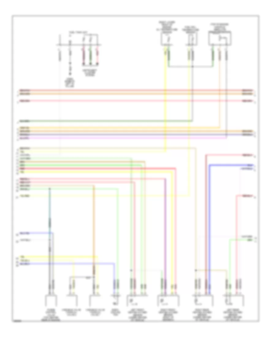
4.4L, Engine Performance Wiring Diagram (3 of 5) for Land Rover Discovery 3 HSE 2009
List of elements for 4.4L, Engine Performance Wiring Diagram (3 of 5) for Land Rover Discovery 3 HSE 2009:
- (center front of engine) c2649
- (left side of engine)
- (right side of engine)
- (right side of engine) c2651
- (top left side of engine)
- (top right side of engine)
- Capacitor
- Fuel injector
- Ignition coil 1
- Ignition coil 2
- Ignition coil 3
- Ignition coil 4
- Ignition coil 5
- Ignition coil 6
- Ignition coil 7
- Ignition coil 8
- Red
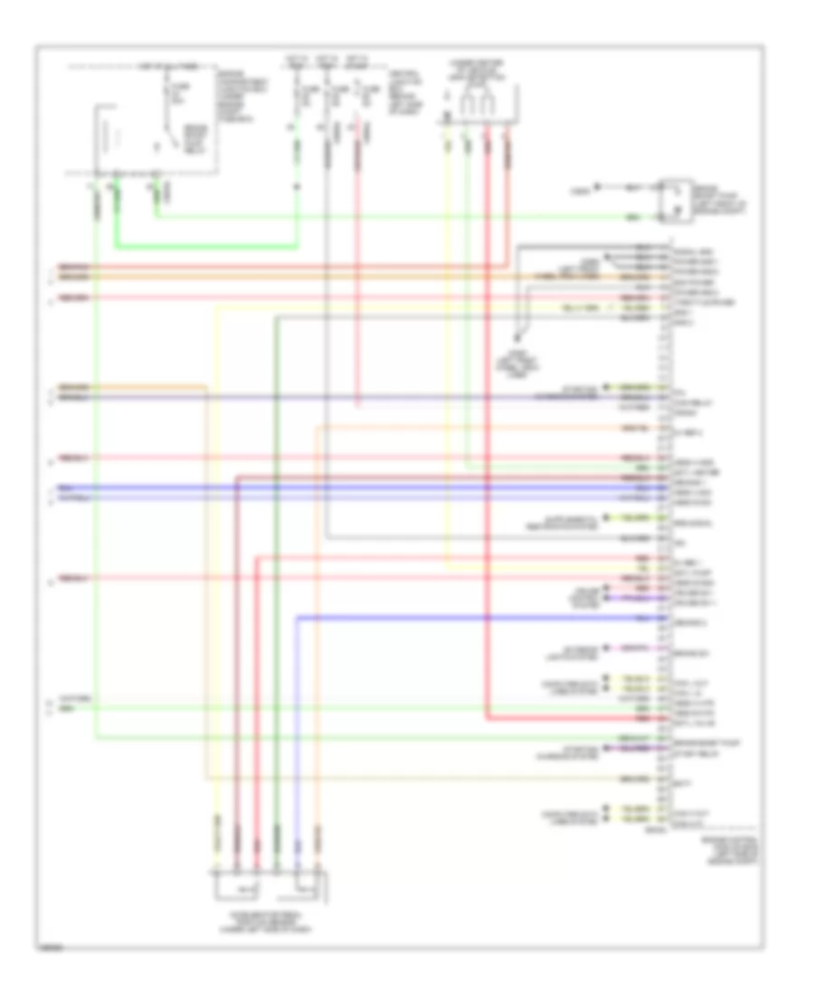
4.4L, Engine Performance Wiring Diagram (4 of 5) for Land Rover Discovery 3 HSE 2009
List of elements for 4.4L, Engine Performance Wiring Diagram (4 of 5) for Land Rover Discovery 3 HSE 2009:
- (right lower front of engine) oil temperature sensor
- (top of engine) manifold absolute pressure sensor
- C2922 (base of left "d" pillar)
- E-box cooling fan
- Fuel rail temperature sensor
- Fuel tank unit
- Instrument cluster system
- Left front heated oxygen sensor (under center of vehicle)
- Left rear heated oxygen sensor (under center of vehicle)
- Purge control valve (top center rear of engine)
- Red
- Right front heated oxygen sensor (right of gearbox)
- Right rear heated oxygen sensor (under center of vehicle)
- Variable valve timing oil valve 1
- Variable valve timing oil valve 2
4.4L, Engine Performance Wiring Diagram (5 of 5) for Land Rover Discovery 3 HSE 2009
List of elements for 4.4L, Engine Performance Wiring Diagram (5 of 5) for Land Rover Discovery 3 HSE 2009:
- (under center of vehicle) leak detection pump
- 5v ref 1
- 5v ref 2
- Accelerator pedal position sensor (under left side of dash)
- Batt
- Brake boost pump
- Brake boost pump (left front of engine compt)
- Brake boost pump relay
- Brake sw
- C0557 (left front wheel arch liner)
- C0570l
- C0583l
- C0584l
- C0635l
- C2635
- C2650 (left front wheel arch liner)
- Can h in
- Can h out
- Can l in
- Can l out
- Central junction box (behind left side of dash)
- Computer data lines system
- Crank
- Cruise control system
- Cruise sw +
- Cruise sw -
- Demand 1
- Demand 2
- Dmtl heater
- Dmtl pump
- Dmtl valve
- Ecm power
- Engine compartment junction box (under engine compt fuse box)
- Engine control module (ecm) (left side of engine compt)
- Exterior lights system
- Fuse 20a
- Fuse 5a
- Gnd 1
- Gnd 2
- Hego a gnd
- Hego a htr
- Hego a sig
- Hego b gnd
- Hego b htr
- Hego b sig
- Hot at all times
- Hot in run
- Hot in start
- Ign
- Main relay
- P/n
- Power gnd 1
- Power gnd 2
- Power gnd 3
- Red
- Signal gnd
- Srs signal
- Start relay
- Starting/ charging system
- Throttle power